Big presser foot component structure of placket machine

A technology with a component structure and a large presser foot, applied in the direction of cloth press mechanism, sewing machine components, textiles and papermaking, etc., can solve the problems of high cost and complex structure, and achieve the effect of simple structure, precise and reliable control, and convenient adjustment.

Active Publication Date: 2018-12-28
BULLMER ELECTROMECHANICAL TECH
View PDF5 Cites 3 Cited by
  • Summary
  • Abstract
  • Description
  • Claims
  • Application Information

AI Technical Summary

Problems solved by technology

[0004] In the above-mentioned patent documents, the left and right movement of the large presser foot i

Method used


Image

  • Big presser foot component structure of placket machine
  • Big presser foot component structure of placket machine
  • Big presser foot component structure of placket machine

Examples


Embodiment 1

[0034] In the traditional structure, the two presser arms of the presser foot part of the placket machine are fastened together by fixing screws, and the two cannot move relatively laterally, so the distance between the left presser foot and the right presser foot cannot be adjusted.

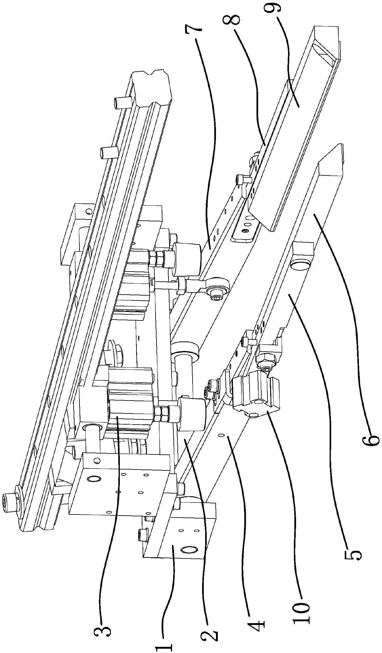
[0035] such as 1 and figure 2 As shown, the fly machine includes a mounting frame 1, and the mounting frame 1 is provided with a hinged shaft 2. The large presser foot assembly structure of the fly machine includes a left large presser arm 4 and a right large presser arm 7 arranged side by side at intervals. One end of the left large presser arm 4 and the right large presser arm 7 is all connected on the hinge shaft 2, and the installation frame 1 is also provided with a hinge that enables the other ends of the left large presser arm 4 and the right large presser arm 7 to be hinged. Shaft 2 swings down the downward pressure cylinder 3; the end of the left large presser arm 4 is connected with t...

Embodiment 2

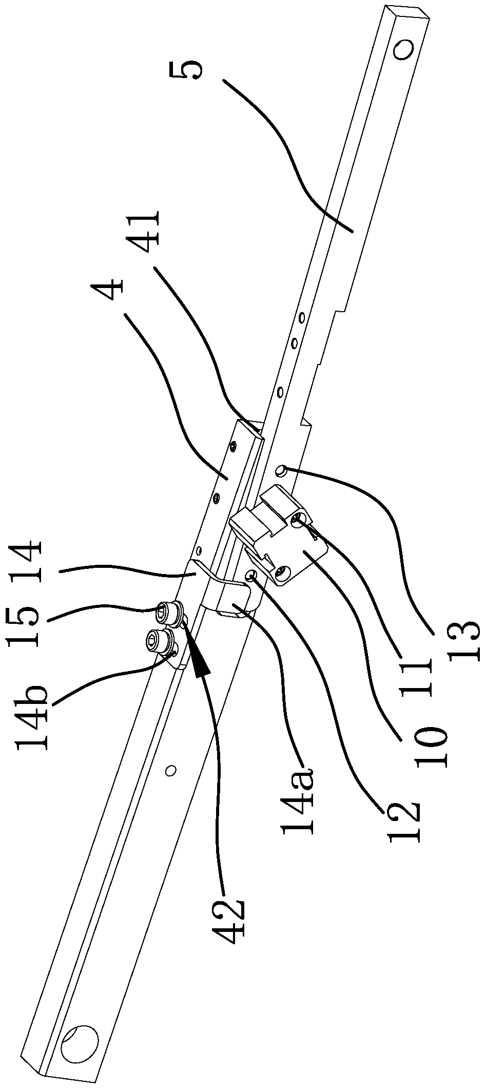
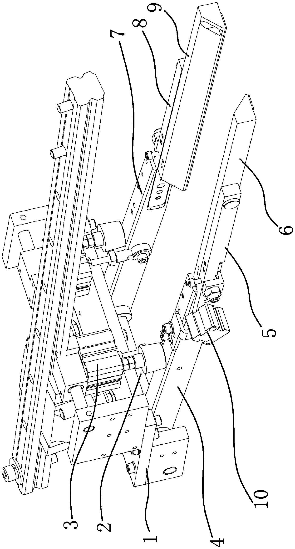
[0042] Such as image 3 and Figure 4 As shown, this embodiment is roughly the same as Embodiment 1, the difference is that in this embodiment, the drive cylinder 10 is fixed on the outer surface of the end of the left large presser arm 4 close to the left small presser arm 5, and the drive cylinder The piston rod end of 10 is fixedly connected with a connecting shaft 16, and the connecting shaft 16 passes through the left large presser foot arm 4 and is fixedly connected with the left small presser foot arm 5, and the left presser foot 6 is connected with the left small presser foot arm 5 through the connecting pin 21. connected and the two can relatively swing around the connecting pin 21. Before the left large presser arm 4 presses down, the driving cylinder 10 moves ahead of time, and the left small presser arm 5 and left small presser arm 6 are driven to move through the driving cylinder 10 and the connecting shaft 16. The left presser foot 6 and the left small presser a...


PUM


Abstract

The invention provides a big presser foot component structure of a placket machine, belongs to the technical field of clothing manufacturing equipment and solves the technical problem that big presserfeet on existing placket machines are poor in cloth pressing effect and inconvenient for interval adjusting. The big presser foot component structure comprises a left big presser foot arm and a rightbig presser foot arm which are arranged side by side at an interval, the end of the left big presser foot arm is connected with a left small presser foot arm, the end of the right big presser foot arm is connected with a right small presser foot arm, a left presser foot is connected on the left small presser foot arm, a right presser foot is connected on the right small presser foot arm, and a driving source enabling the left presser foot and the right presser foot to be in relative reciprocating motion is arranged between the left big presser foot arm and the left small presser foot arm or/and between the right big presser foot arm and the right small presser foot arm. The big presser foot component structure is simple in structure, stable and reliable, relative motion of the left presser foot and the right presser foot can be realized through a driving cylinder, and flattening of cloth and adjusting of a distance between the left presser foot and the right presser foot are realized.

Description

technical field [0001] The invention belongs to the technical field of garment manufacturing equipment, and relates to a fly machine, in particular to a large presser foot assembly structure of the fly machine. Background technique [0002] The opening of the front chest of the clothes is called the placket. The placket is the most eye-catching main part in many clothing decorations. It sets off with the collar and the pocket to show the gorgeous appearance of the fashion. The styles of the placket are endless and ever-changing. At present, there are two ways to process the placket. One is to sew by hand with an ordinary sewing machine, and the other is to sew automatically by an automatic placket machine; It is a sewing machine specially designed and developed for the placket, which can reduce the processing procedures and simplify the production process, thereby effectively improving work efficiency. The placket machine usually includes a large presser foot component stru...

Claims


Application Information

Patent Timeline
IPC IPC(8): D05B29/02D05B29/08
CPCD05B29/02D05B29/08
Inventor 叶彬
Owner BULLMER ELECTROMECHANICAL TECH
Why Eureka
Try Eureka