
Door locking structure device

A door locking and door frame technology, which is applied to door/window fittings, building structures, power control mechanisms, etc., can solve the problems of single design and insufficient development status, and achieve the effect of simple structure, easy use, and convenience.

Inactive Publication Date: 2018-12-28
屠建芳
View PDF0 Cites 1 Cited by
  • Summary
  • Abstract
  • Description
  • Claims
  • Application Information

AI Technical Summary

Problems solved by technology

[0002] The door closing device currently on the market has a single design and a simple structure. Compared with the current automation and industrialization development background, this device shows a serious shortage of development status. Therefore, further improvements are made for the existing door locking device products on the market. , so that it can complete the development of automation, safety and humanization

Method used


Image

  • Door locking structure device
  • Door locking structure device
  • Door locking structure device

Examples


Embodiment Construction

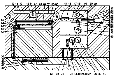
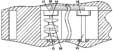
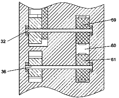
[0014] Such as Figure 1-3 As shown, a door locking structure device of the present invention includes a door frame 10, a ground 62 is provided below the door frame 10, a first sliding cavity 49 is provided in the ground 62, and the lower end wall of the first sliding cavity 49 A first hydraulic chamber 46 is provided, a pedal 50 is slid in the first sliding cavity 49, a connecting rod 48 is fixed on the lower end wall of the pedal 50, and a first hydraulic chamber 46 is slid A hydraulic plate 47. The upper end wall of the first hydraulic plate 47 is fixedly connected to the connecting rod 48. A first hydraulic tank 44 is fixed between the door frame 10 and the ground 62. The first hydraulic tank 44 is A second hydraulic chamber 41 is provided. A first hydraulic pipe 45 is provided between the second hydraulic chamber 41 and the first hydraulic chamber 46, and a second hydraulic pipe 45 is slidably provided in the second hydraulic chamber 41. The second hydraulic plate 42 is f...


PUM


Abstract

The invention discloses a door locking structure device which comprises a door frame. A floor is arranged under the door frame, a first sliding cavity is arranged in the floor, a first hydraulic cavity is arranged in the lower endwall of the first sliding cavity, a pedal is slidably arranged in the first sliding cavity, a connecting rod is fixedly arranged on the lower endwall of the pedal, a first hydraulic plate is slidably arranged in the first hydraulic cavity, the upper endwall of the first hydraulic plate is fixedly connected with the connecting rod, a first hydraulic box is fixedly arranged between the door frame and the floor, a second hydraulic cavity is arranged in the first hydraulic box, a first hydraulic pipe is arranged between the second hydraulic cavity and the first hydraulic cavity in a communicating manner, a second hydraulic plate is slidably arranged in the second hydraulic cavity and is fixedly arranged on the first hydraulic pipe, and a first gear cavity is arranged in the door frame and located above the first hydraulic box.

Description

Technical field [0001] The invention relates to the opening and closing and locking of doors, in particular to a door locking structure device. Background technique [0002] The door closing device currently on the market has a single design and simple structure. Compared with the current automation and industrial development, the device reflects the serious lack of development status. Therefore, the existing door locking device products on the market are further improved. , Make it complete the development of automation, security and humanization. Summary of the invention [0003] In view of the above technical deficiencies, the present invention proposes a door locking structure device. [0004] A door locking structure device of the present invention includes a door frame, a ground is provided below the door frame, a first sliding cavity is provided in the ground, and a first hydraulic cavity is provided on the lower end wall of the first sliding cavity. A pedal is slid in the ...

Claims


Application Information

Patent Timeline
Patent Type & Authority Applications(China)
IPC IPC(8): E05F15/56
CPCE05F15/56E05Y2900/132
Inventor 屠建芳
Owner 屠建芳
Learn More