Axial-flow centrifugal separator and oil-gas separation method

An oil-gas separator and axial flow technology, which is applied in the direction of machines/engines, variable-capacity pump components, liquid variable-capacity machinery, etc., can solve problems such as pressure loss and secondary entrainment, so as to prolong service life and improve efficiency , high work efficiency

Active Publication Date: 2019-08-23
烟台冰轮环保科技有限公司
View PDF8 Cites 0 Cited by
  • Summary
  • Abstract
  • Description
  • Claims
  • Application Information

AI Technical Summary

Problems solved by technology

At the same time, it solves the problem that the separated oil droplets are re-carried by the high-speed airflow into the oil-air mixture to cause secondary entrainment, and the problem of inevitable pressure loss when the rotating airflow enters the filter element

Method used


Image

  • Axial-flow centrifugal separator and oil-gas separation method
  • Axial-flow centrifugal separator and oil-gas separation method
  • Axial-flow centrifugal separator and oil-gas separation method

Examples


Embodiment Construction

[0030] The following figures will further illustrate the present invention in conjunction with the accompanying drawings.

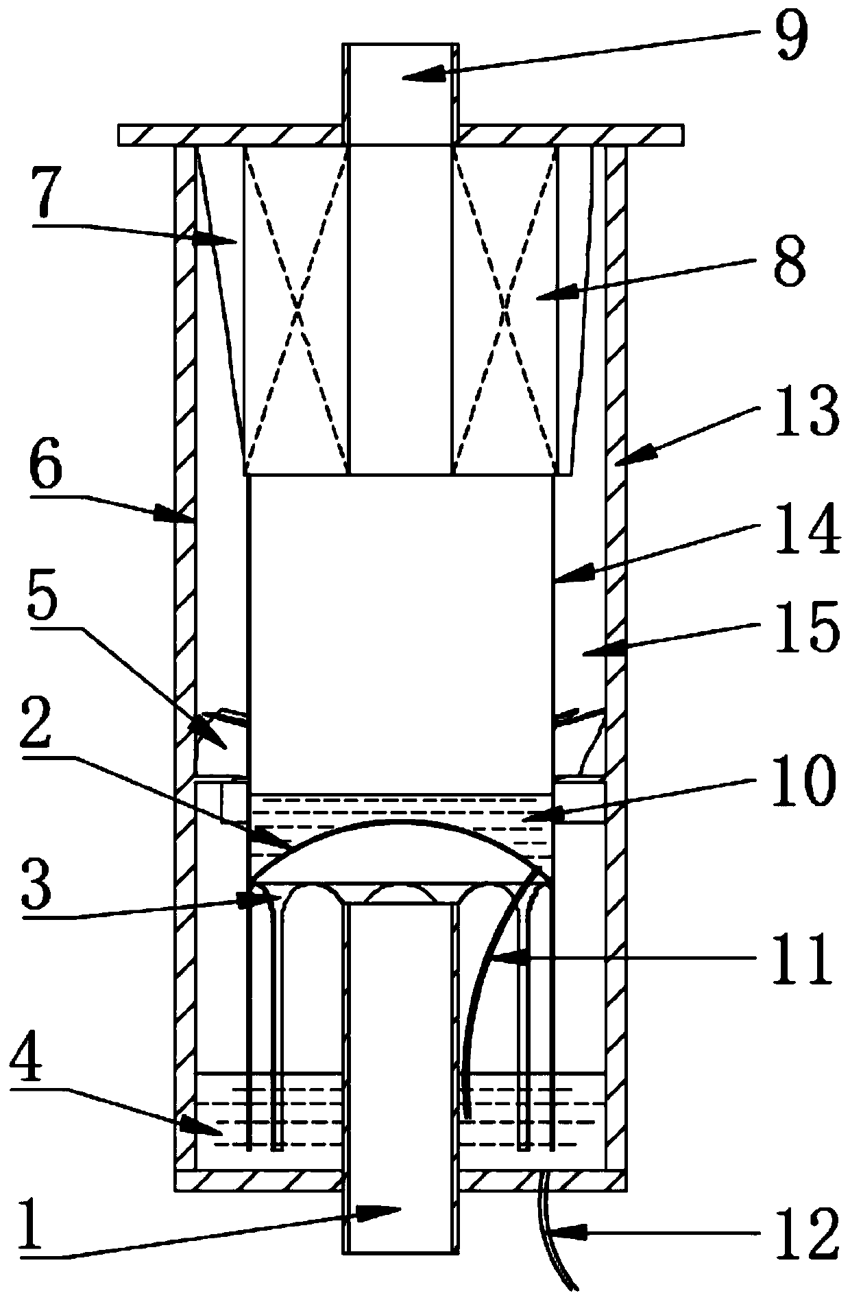
[0031] Existing oil-gas separators for oil-injected compressors usually use a combination of cyclone separators and filter elements for separation, which has poor adaptability to compressors with a large range of operating conditions. The problem of re-entrainment of air flow into the oil-air mixture and the inevitable pressure loss when the rotating air flow enters the filter element. For this reason, the present invention proposes the following axial-flow centrifugal oil-gas separator.

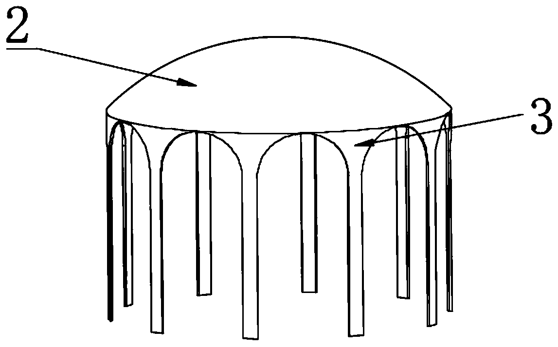
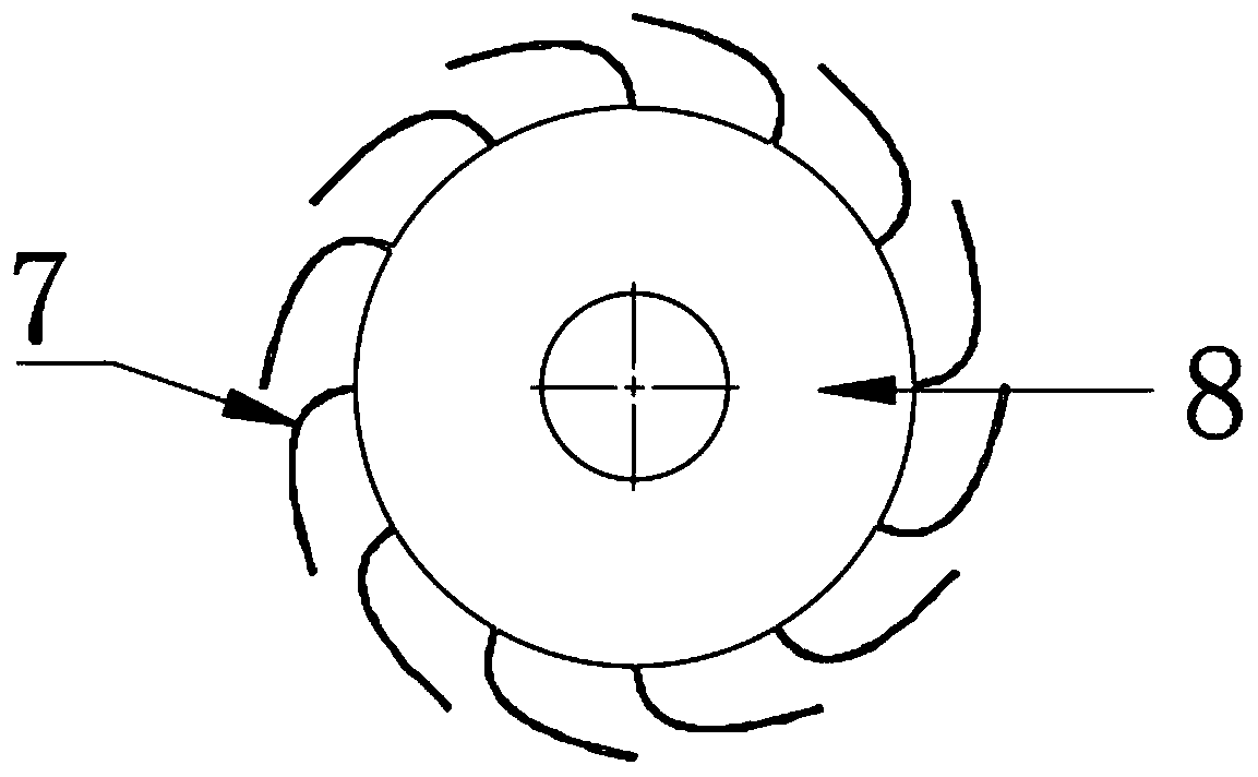
[0032] see figure 1 , the axial-flow centrifugal oil-gas separator of the present invention comprises an outer cylinder 13, an inner cylinder 14, an arc surface coarse separation device, a cyclone, a deflector and a filter element 8, and the outer cylinder 13 and the inner cylinder 14 are cylindrical cylinders , the upper and lower ends of the outer cylinder 13 are re...


PUM


Abstract

The invention relates to the field of two-phase separation equipment, in particular to an axial-flow-type centrifugal separator and an oil-gas separating method. The top of an arc-shaped baffle is upwards protruded and connected with the lower end of an inner tube. Oil guiding strips are evenly distributed in the circumferential direction of the baffle, the upper ends of the oil guiding strips areconnected with the outer edge of the baffle, and the lower ends of the oil guiding strips extend to the lower end of an outer tube. A gas inlet penetrates through the lower end face of the outer tube, and the upper end of the gas inlet extends to the lower portion of the baffle. A cyclone is arranged in an annular area formed between the outer tube and the inner tube. A filter element is arrangedbetween the upper end of the inner tube and the upper end face of the outer tube, and a gas outlet is connected with the filter element. A flow guiding device is arranged outside the filter element and used for rectifying a rotational flow. The capacity of an oil-gas separator to adapt to variable working condition operating of a compressor is effectively improved through an inlet coarse separation device and a centrifugal separation area; and the flow guiding device rectifies the rotational flow at a centrifugal separation section, the loss of the separator is effectively lowered, the separation effect of the filter element is enhanced indirectly, and the service life of the filter element is prolonged.

Description

technical field [0001] The invention relates to the field of two-phase separation equipment, in particular to an axial-flow centrifugal separator and an oil-gas separation method. Background technique [0002] When the oil-injected compressor is working, lubricating oil is sprayed into it to cool down, lubricate and seal the compressor. After being compressed by the rotor, the two-phase mixture of compressed air and lubricating oil is separated by an oil-air separator. In order to improve the quality of compressed air and ensure the safe operation of the compressor, it is necessary to separate the liquid phase oil droplets as much as possible, which puts forward strict requirements on the separation efficiency of the oil-gas separator. The compressor is designed under rated working conditions, but in actual operation, the intake and exhaust pressure will change according to the actual use requirements, resulting in fluctuations in the displacement. Therefore, the separatio...

Claims


Application Information

Patent Timeline
Patent Type & Authority Patents(China)
IPC IPC(8): F04B39/04F04B39/16
Inventor 冯健美陈伟彭学院韩济泉
Owner 烟台冰轮环保科技有限公司
Why Eureka
Try Eureka