

A special coil box for an ignition transformer
A wire coil box and transformer technology, applied in the field of transformers, can solve problems such as damage and failure, and achieve the effect of protecting lines, complete functions, and simple structure
Inactive Publication Date: 2018-12-28
SUZHOU HUANYAN ELECTRIC
View PDF0 Cites 0 Cited by
- Summary
- Abstract
- Description
- Claims
- Application Information
AI Technical Summary
Problems solved by technology
Existing finished ignition transformers are usually square devices with input and output wiring on the same side. In order to expand the scope of application, the wiring is usually set longer and needs to be coiled and fixed. Therefore, during the production process and transportation process, the wiring often appears Damage and failure problems caused by collision wear and other conditions
Method used
View moreImage
Smart ImageViewing Examples

Examples
Embodiment Construction
Login to View More PUM
 Abstract
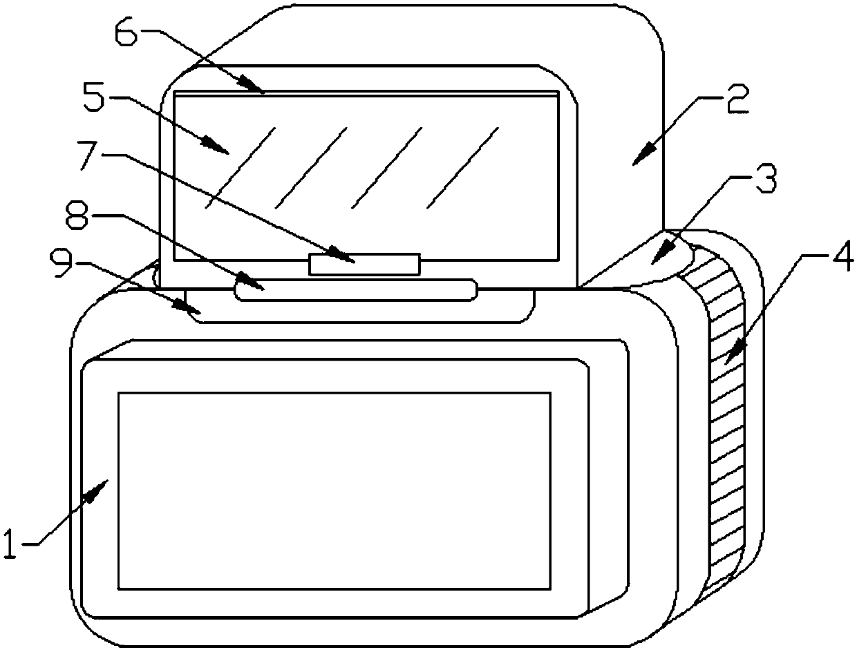
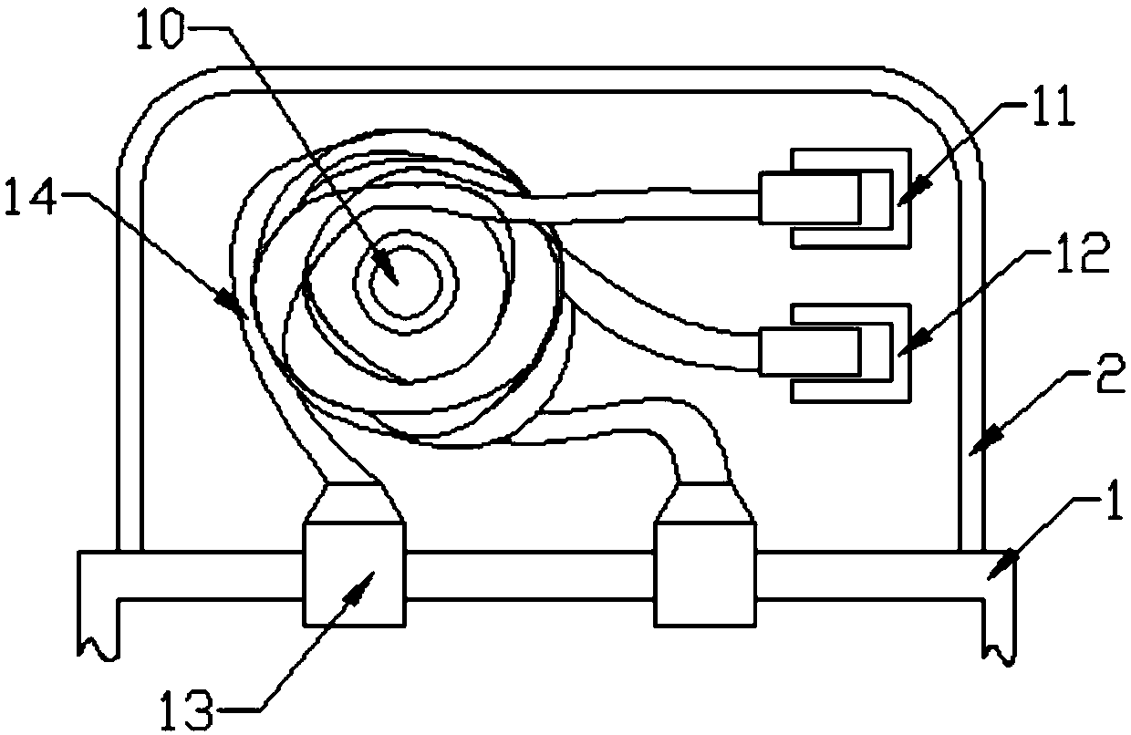
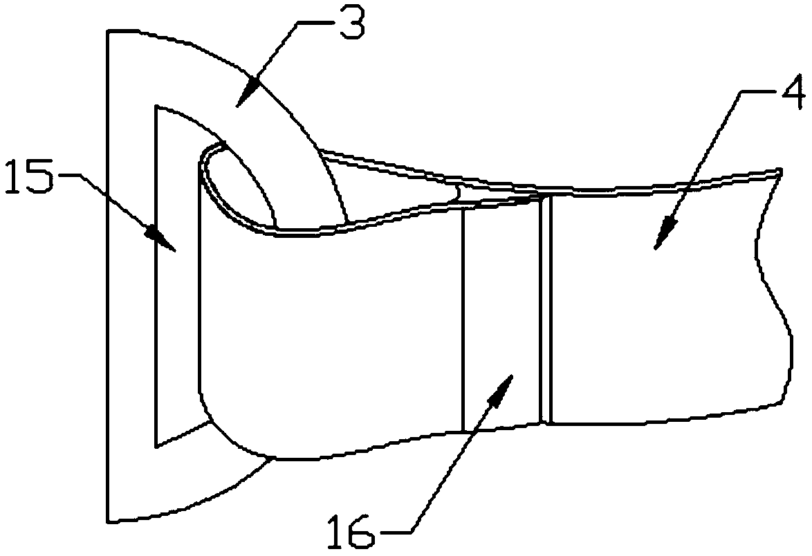
The invention discloses a special coil box for an ignition transformer, which includes a coil box, an ignition transformer is arranged at the bottom of the coil box, a positioning plate is arranged onboth side of the coil box, a fastening belt is installed on the outside of the positioning plate, the fastening belt is made of elastic rubber tape, a positioning edge is installed on the bottom of the coil box, a detection cover is installed on the surface of the coil box, a winding column is installed inside the coil box, and an input end clasp and an output end clasp are installed inside the coil box. The coil box can be fully fixed on the ignition transformer by the cooperation of the positioning edge protector and the fastening belt, the transparent detection cover enables people to visually observe the condition of the signal cable, and can be opened and closed conveniently with the snap fastener, so that the signal cable is convenient to arrange and the simple quality inspection operation is carried out, the coil box is simple in structure but complete in function, can effectively protect the circuit, and the cost is relatively low, the process is simple and convenient to produce, and has the popularization value.
Description
technical field The invention relates to the technical field of transformers, in particular to a coil box dedicated to ignition transformers. Background technique The main functions of the transformer are voltage transformation, impedance transformation, isolation and voltage regulation, etc. Transformers are widely used in the automatic control of burners, and there are many types and types. The ignition transformer is mainly used in the ignition system of the burner to realize the function of automatic ignition of the burner. Existing finished ignition transformers are usually square devices with input and output wiring on the same side. In order to expand the scope of application, the wiring is usually set longer and needs to be coiled and fixed. Therefore, during the production process and transportation process, the wiring often appears Damage and failure problems caused by collision wear and other conditions. Therefore, how to design a special coil box for the ignit...
Claims
Login to View More Application Information
Patent Timeline
 Patent Type & AuthorityApplications(China)
IPC IPC(8): H02G3/08H01F27/28
CPCH02G3/08H01F27/28
Inventor颜欢
OwnerSUZHOU HUANYAN ELECTRIC