
Inner and outer core pulling type injection molding mold and inner core pulling shaping structure

A technology for molding structures and injection molds, which is applied to household appliances, other household appliances, household components, etc., can solve the problems of complexity and high manufacturing cost of core-pulling mechanisms, and achieve low manufacturing costs, high molding quality, and high structural compactness Effect

Active Publication Date: 2019-01-01
STARWAY INTERNATIONAL HOME LIVING CO LTD
View PDF4 Cites 0 Cited by
  • Summary
  • Abstract
  • Description
  • Claims
  • Application Information

AI Technical Summary

Problems solved by technology

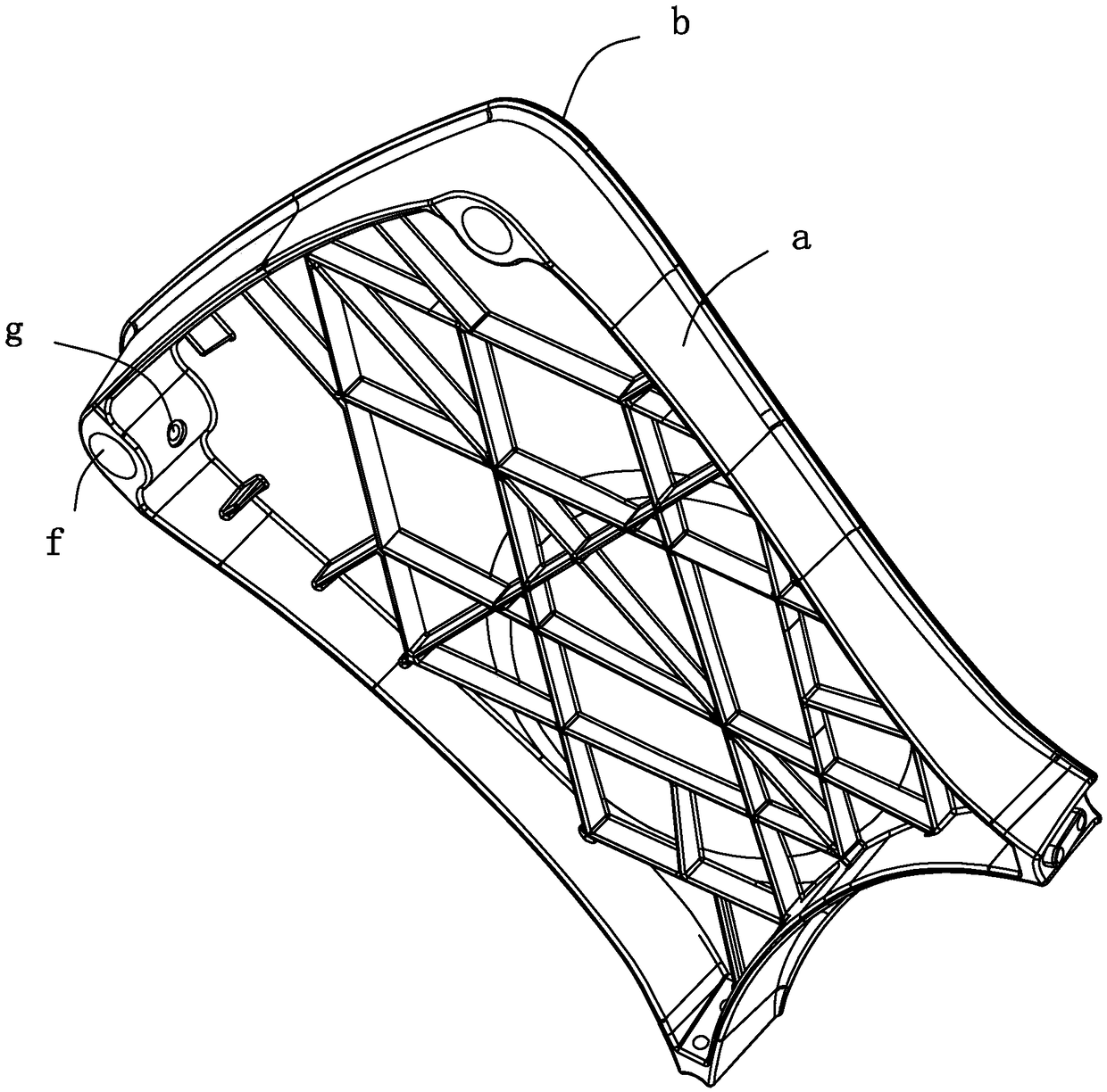
[0006] The traditional injection mold used to form the corresponding product usually adopts a side-drawing mechanism. For the structure of the above-mentioned seat surface, the difficulty in mold design is that the fastening hole g faces the middle of the seat surface, and it is necessary to form the characteristics of the above-mentioned fastening hole g. A more complex core-pulling structure will be designed, and the manufacturing cost of complex core-pulling mechanisms is high

Method used


Image

  • Inner and outer core pulling type injection molding mold and inner core pulling shaping structure
  • Inner and outer core pulling type injection molding mold and inner core pulling shaping structure
  • Inner and outer core pulling type injection molding mold and inner core pulling shaping structure

Examples


Embodiment 1

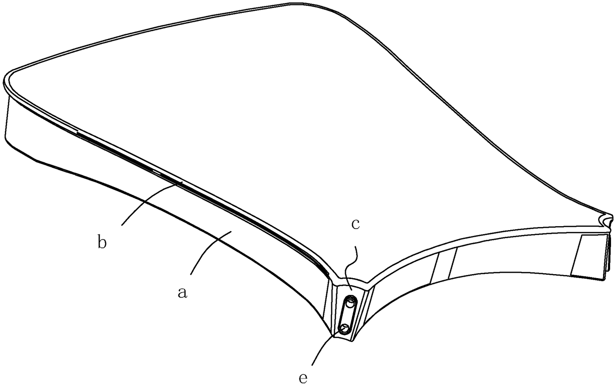
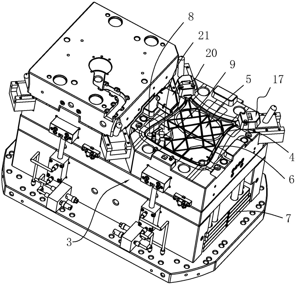
[0057] An inner core-pulling forming structure for forming such as figure 1 Inserting hole f and fastening hole g of the seat surface, see image 3 , which includes a first movable mold 3, an installation groove 4 is provided on the first movable mold 3, a core 5 is installed in the installation groove 4, and a molding cavity 6 is formed between the outer wall of the core 5 and the groove wall of the installation groove 4, forming Cavity 6 is used to form such as figure 1 as well as figure 2 The seat surface, the inner core-pulling molding structure is installed in the core 5.

[0058] see image 3 as well as Figure 4 , the inner core-pulling forming structure includes a forming rod 8, a driving rod 10, and a first driving part 44. One end of the forming rod 8 extends into the molding cavity 6 and is used to form the insertion hole f, and the other end of the forming rod 8 is connected to the first driving part 44. Section 44. One end of the drive rod 10 is inserted in...

Embodiment 2

[0064] An inner and outer core pulling injection mold for injection molding such as figure 1 as well as figure 2 The chair surface shown here.

[0065] see image 3 as well as Image 6 , its structure includes a first molding die 1, the first molding die 1 includes a first fixed mold 2, the first fixed mold 2 and the first movable mold 3 can be molded or parted with each other, and an external core-pulling structure 17 is included. The inner core-pulling molding structure in Example 1.

[0066] Among them, see Image 6 as well as Figure 7 , the first movable mold 3 includes a first mold base 14, a primary template 15 in a relatively fixed state relative to the first mold base 14, a secondary template 16 in a relatively movable state relative to the first mold base 14, and the outer core pulling The structure 17 includes a sliding seat 18 and an inclined guide post 19. The sliding seat 18 is slidably connected to the secondary formwork 16, one end of the inclined guide ...

Embodiment 3

[0076] Embodiment 3: The difference from Embodiment 1 and Embodiment 2 is that, see Figure 12 , a tank body 48 is provided in the tank cover 20, the end of the driving bolt 132 away from the forming block 12 is located in the tank body 48, the driving spring 131 is located in the tank body 48, and an elastic air bag 49 is also arranged in the tank body 48, and the driving bolt 132 is deviated from the end of forming block 12 and can produce extrusion force to elastic airbag 49, and the integral volume of elastic airbag 49 can become smaller, when elastic airbag 49 is not subjected to extrusion force, can return to original shape; 20 is provided with a blowing channel 50, one end of the blowing channel 50 is docked inside the elastic air bag 49, the other end of the blowing channel 50 faces the first boss 45, and the mouth of the blowing channel 50 near the first boss 45 is provided with One-way outlet valve 51.

[0077] When the forming block 12 moves away from the forming c...


PUM


Abstract

The invention discloses an inner and outer core pulling type injection molding mold and inner core pulling shaping structure, and relates to the technical field of an injection molding mold. The innercore pulling shaping structure is characterized by comprising a first movable mold, wherein an installing groove is formed in the first movable mold; a die core is arranged in the installing groove;the structure also comprises a shaping rod, a driving rod and a first driving part; the other end of the shaping rod is connected with a first driving part; one end of the driving rod is inserted intothe die core; the end part is provided with an inclined guide surface; the inclined guide surface faces one side backing to the first movable mold; the other end of the driving rod is connected withthe first driving part; a shaping block and an elastic driving element are arranged in the die core; the elastic driving element is used for pulling the shaping block to be always attached to the inclined guide surface; the first driving part is used for driving the shaping rod; the driving rod moves towards one side backing to or approaching to the die core. By using the structure, the whole volume of the inner core pulling shaping structure is greatly reduced; the structure is ingenious; the compact degree is high. Compared with a conventional complicated core pulling structure, the structure has the advantage that the manufacturing cost is greatly reduced.

Description

technical field [0001] The invention relates to the technical field of injection molds, in particular to an inner and outer core-pulling injection mold and an inner core-pulling forming structure thereof. Background technique [0002] Injection mold is a tool for producing plastic products, and it is also a tool for giving plastic products complete structure and precise dimensions. [0003] The traditional injection mold structure for injection molding of square chair surface products is usually divided into a fixed mold and a movable mold. The fixed mold is provided with a gate, and the parting surface between the fixed mold and the movable mold will be located in the middle of the seat surface. [0004] see figure 1 , the product is the seat surface inside the plastic chair. The overall shape of the chair surface is roughly square, and it is used for the user to sit on the buttocks. [0005] Considering the installation stability of the two front chair legs, an insertion...

Claims


Application Information

Patent Timeline
Patent Type & Authority Applications(China)
IPC IPC(8): B29C45/28B29C45/33B29C45/16B29C45/40B29L31/44
CPCB29C45/1615B29C45/2806B29C45/33B29C45/4005B29L2031/443
Inventor 叶根林
Owner STARWAY INTERNATIONAL HOME LIVING CO LTD
Learn More