Automatic membrane tearing device

A film device and automatic technology, which is applied in packaging, transportation and packaging, and unsealing of objects, etc., can solve the problems of low work efficiency, high labor cost, and high labor intensity of manual film tearing, so as to improve work efficiency and reduce labor intensity and human cost effects

Active Publication Date: 2019-01-01
TCL KING ELECTRICAL APPLIANCES HUIZHOU
View PDF4 Cites 0 Cited by
  • Summary
  • Abstract
  • Description
  • Claims
  • Application Information

AI Technical Summary

Problems solved by technology

[0004] The main purpose of the present invention is to provide an automatic film tearing device, which aims to solve the problems of high labor intensity, high labor cost and low work efficiency of the existing artificial film tearing

Method used


Image

  • Automatic membrane tearing device
  • Automatic membrane tearing device
  • Automatic membrane tearing device

Examples


Embodiment Construction

[0028] The following will clearly and completely describe the technical solutions in the embodiments of the present invention with reference to the accompanying drawings in the embodiments of the present invention. Obviously, the described embodiments are only part of the embodiments of the present invention, not all of them. Based on the embodiments of the present invention, all other embodiments obtained by persons of ordinary skill in the art without creative efforts fall within the protection scope of the present invention.

[0029] It should be noted that all directional indications (such as up, down, left, right, front, back...) in the embodiments of the present invention are only used to explain the relationship between the components in a certain posture (as shown in the accompanying drawings). Relative positional relationship, movement conditions, etc., if the specific posture changes, the directional indication will also change accordingly.

[0030] In addition, in t...


PUM


Abstract

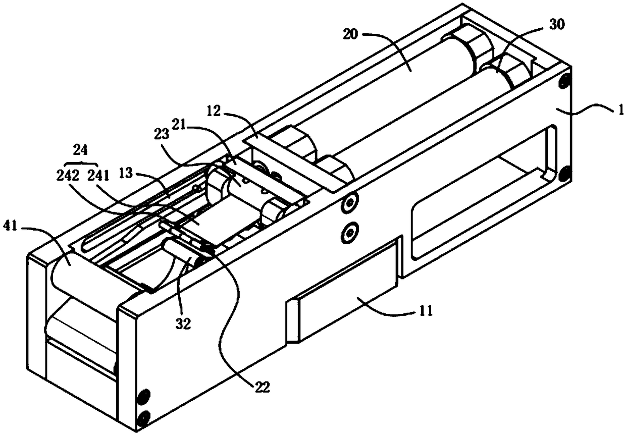
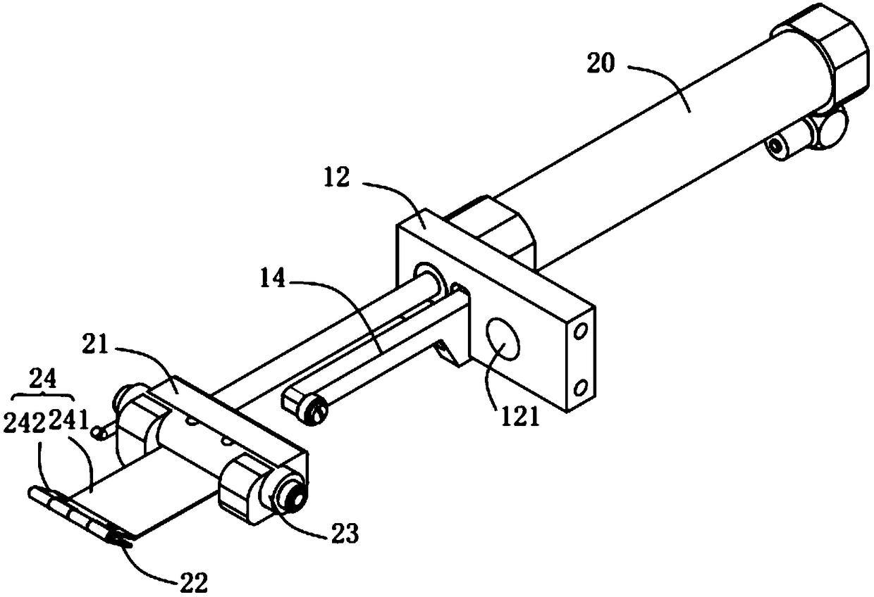
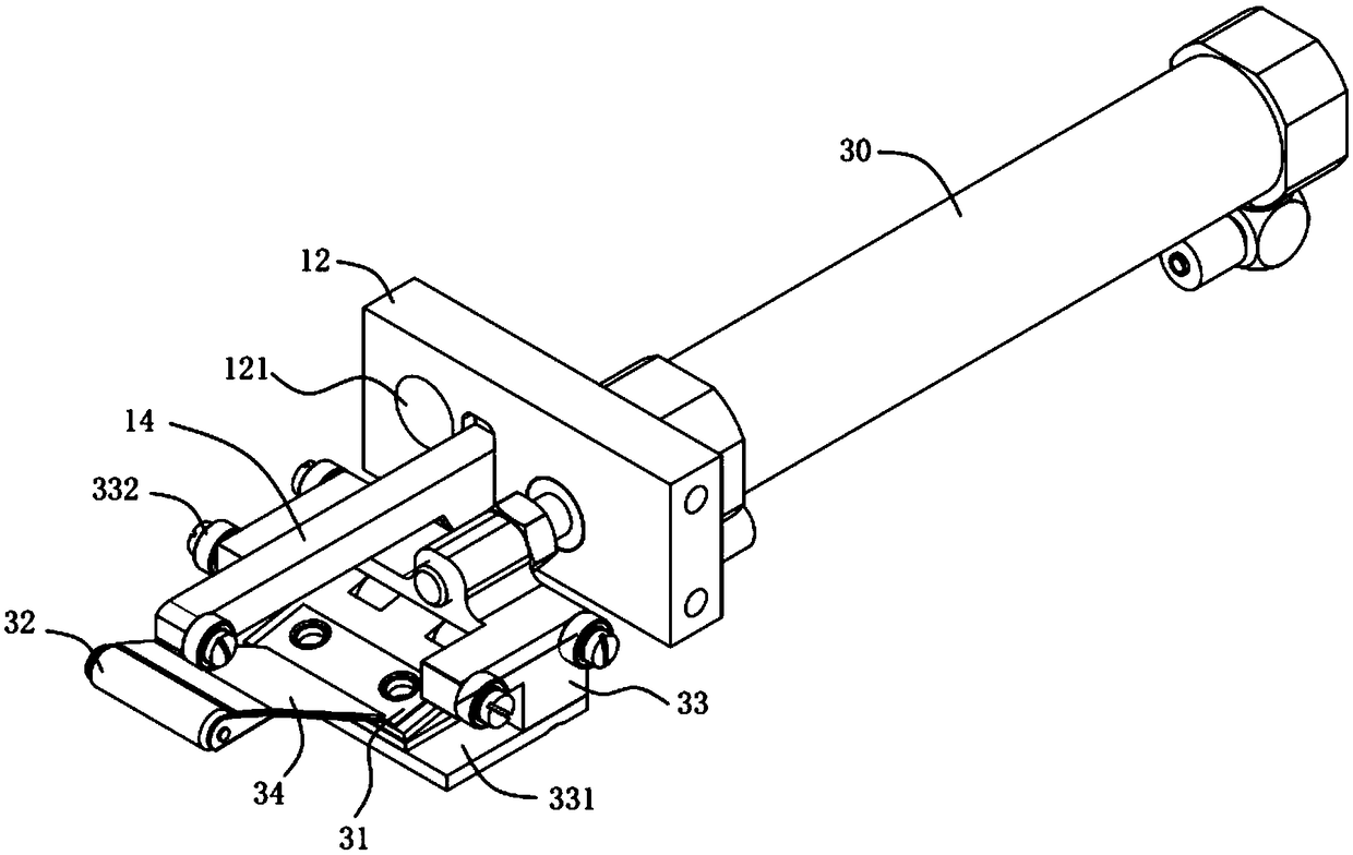
The invention provides an automatic membrane tearing device. The automatic membrane tearing device comprises a movable base frame, an adhesive tape taking mechanism and an adhesive tape press fittingmechanism, wherein the adhesive tape taking mechanism comprises a first telescopic driving device arranged on the movable base frame, and an adhesive tape taking part connected to a telescopic part ofthe first telescopic driving device, so that the adhesive tape taking part is driven to be stuck to the sticking surface of an adhesive tape through the extension movement of the first telescopic driving device, and the adhesive tape is driven to enter the automatic membrane tearing device through the retraction movement of the first telescopic driving device; the adhesive tape press fitting mechanism comprises a second telescopic driving device arranged on the movable base frame, and an adhesive tape press fitting part connected to a telescopic part of the second telescopic driving device, so that the adhesive tape press fitting part is driven to stick the adhesive tape to a membrane to be torn through the extension movement of the second telescopic driving device, and thus, the membraneto be torn can be torn through the movement of the movable base frame. The automatic membrane tearing device realizes the automatic membrane tearing, reduces the labor intensity and improves the working efficiency.

Description

technical field [0001] The invention relates to the field of film tearing devices, in particular to an automatic film tearing device. Background technique [0002] A display device generally includes a liquid crystal panel and a display backplane. Before installing the liquid crystal panel on the display backplane, it is necessary to tear off the protective film on the surface of the liquid crystal panel. Generally, the protective film on the surface of the liquid crystal panel is an electrostatic film, which is a kind of non-adhesive film. It relies on the electrostatic adsorption of the product itself to stick to the object for protection. There is no static electricity on the outside of the electrostatic film, and it is a self-adhesive film with low adhesion. [0003] However, at present, the tearing process of the liquid crystal panel is manually completed, especially when tearing a large-size liquid crystal panel, which is labor-intensive for the operators of the assem...

Claims


Application Information

Patent Timeline
IPC IPC(8): B65B69/00
CPCB65B69/00
Inventor 叶振强李竞帆庄子开
Owner TCL KING ELECTRICAL APPLIANCES HUIZHOU
Why Eureka
Try Eureka