
Composite material evacuation platform for subway tunnel

A technology for evacuation platforms and composite materials, applied in safety devices, mining equipment, earthwork drilling and mining, etc., can solve problems such as long construction period, inconvenient cutting, long maintenance cycle and long production cycle, so as to improve production efficiency and product quality , good continuity and integrity, and the effect of reducing labor costs and labor intensity

Pending Publication Date: 2021-06-11
DE RUISEN NANTONG COMPOSITE MATERIAL CO LTD
View PDF0 Cites 0 Cited by
  • Summary
  • Abstract
  • Description
  • Claims
  • Application Information

AI Technical Summary

Problems solved by technology

[0003] In terms of composition and connection mode, the cement-based platform is lapped on the cement-based pier at both ends, and the cement-based pier is fixed on the tunnel wall through anchor bolts, so its strength is high, but the disadvantage is that it needs to make molds, cast molding, and maintain The cycle and production cycle are long, cutting is inconvenient, and the buttresses are made of fixed molds, which are not suitable for changing curved horseshoe shapes
In the prefabricated reinforced concrete structure, the platform is lapped on the horizontal support piers at both ends, and the support piers lean on the shield segments. It has the advantages of high strength and good fire resistance, but the disadvantage is that the construction period is long and the cost is high

Method used


Image

  • Composite material evacuation platform for subway tunnel
  • Composite material evacuation platform for subway tunnel
  • Composite material evacuation platform for subway tunnel

Examples


Embodiment Construction

[0017] The following will clearly and completely describe the technical solutions in the embodiments of the present invention with reference to the accompanying drawings in the embodiments of the present invention. Obviously, the described embodiments are only some, not all, embodiments of the present invention. Based on the embodiments of the present invention, all other embodiments obtained by persons of ordinary skill in the art without making creative efforts belong to the protection scope of the present invention.

[0018] In the description of the present invention, it should be noted that the terms "upper", "lower", "inner", "outer", "front end", "rear end", "both ends", "one end", "another end" The orientation or positional relationship indicated by etc. is based on the orientation or positional relationship shown in the drawings, and is only for the convenience of describing the present invention and simplifying the description, rather than indicating or implying that ...


PUM

PropertyMeasurementUnit
Heightaaaaaaaaaa
Lengthaaaaaaaaaa
Widthaaaaaaaaaa

Abstract

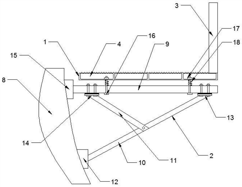
The invention discloses a composite material evacuation platform for a subway tunnel. The composite material evacuation platform for the subway tunnel comprises an evacuation platform body, a supporting assembly and a guardrail rod; four square cavities are evenly distributed in the evacuation platform body; U-shaped grooves which are symmetrical relative to the center of the evacuation platform body are formed in the positions, close to the inner sides of the square cavities on the outer sides, on the two sides of the bottom face of the evacuation platform body; an anti-skid platform face is arranged on the evacuation platform body; anti-skid protruding strips are arranged on the anti-skid platform face; a supporting assembly is connected to the bottom of the evacuation platform body; and the guardrail rod is fixedly connected to the side, away from the tunnel wall, of the evacuation platform body. The evacuation platform adopts an integral plate formed by one-step molding through a pultrusion process and is sealed on the surface, the surface of a standard product is an anti-slip surface, and anti-slip raised lines are arranged on the platform surface. Due to the fact that the forming process of a mold for producing the product is one-step forming, the continuity and integrity are very good, labor cost and labor intensity are greatly reduced, and the production efficiency and product quality are improved.

Description

technical field [0001] The invention relates to the technical field of evacuation platforms, in particular to a composite material evacuation platform for subway tunnels. Background technique [0002] At present, there are three main schemes for the evacuation platform of the underground section of the subway in China: 1. Prefabricated cement-based structure; 2. Prefabricated reinforced concrete structure; 3. Composite material structure. [0003] In terms of composition and connection mode, the cement-based platform is lapped on the cement-based pier at both ends, and the cement-based pier is fixed on the tunnel wall through anchor bolts, so its strength is high, but the disadvantage is that it needs to make molds, cast molding, and maintain The cycle and production cycle are long, cutting is inconvenient, and the buttresses are made of fixed molds, which are not suitable for the changeable arc horseshoe. In the prefabricated reinforced concrete structure, the platform is ...

Claims


Application Information

Patent Timeline
IPC IPC(8): E21F11/00
CPCE21F11/00
Inventor 周建军
Owner DE RUISEN NANTONG COMPOSITE MATERIAL CO LTD
Learn More