Electroplating tank body automatic water inlet and water outlet mechanism and device

A water outlet mechanism and automatic technology, applied in cranes, electrolysis processes, electrolysis components, etc., can solve the problems of low degree of automation, high labor intensity, and high labor costs, and achieve less chemical residues, labor intensity and labor costs, and loading and unloading. Product convenience effect

Pending Publication Date: 2018-08-28
苏州南盛自动化科技有限公司
View PDF0 Cites 1 Cited by
  • Summary
  • Abstract
  • Description
  • Claims
  • Application Information

AI Technical Summary

Problems solved by technology

[0005] The purpose of the present invention is to overcome the defects of low degree of equipment automation, high labor intensity and high labor cost in the prior art, and provide a mechanism and device for automatic water inlet and outlet of electroplating pots with high production efficiency and high automation

Method used


Image

  • Electroplating tank body automatic water inlet and water outlet mechanism and device
  • Electroplating tank body automatic water inlet and water outlet mechanism and device
  • Electroplating tank body automatic water inlet and water outlet mechanism and device

Examples


Embodiment 1

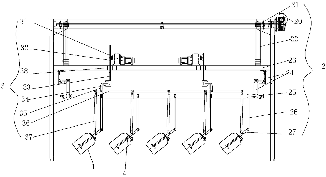
[0033] Such as Figure 1-Figure 3 The specific embodiment of the automatic water inlet and outlet mechanism of the electroplating tank shown in the present invention includes: a lifting assembly 2, a thrust assembly 3 and a clamp 4 for fixing the can-shaped product 1, and the lifting assembly 2 includes: a lifting motor 20, The reel 21 coaxially connected with the output shaft of the lifting motor 20, the lifting sling 22 wound on the reel 21, the fixed main rod 23 fixed at the end of the lifting sling 22, the fixed main rod 23 fixed below the fixed main rod 23 through the lifting bracket 24 Lifting bar 25, a plurality of lifting plates 26 arranged and fixed on the lifting bar 25, and a main conductive rod 27 rotatably connected to the end of the lifting plate 26; Motor 31, the gear 32 that is coaxially connected with the output shaft of thrust motor 31, the rack 33 that meshes with gear 32, the suspension hook 34 that is fixed on the lower end of the rack 33, the fixed frame ...

Embodiment 2

[0039] Such as Figure 4 As shown, the difference between embodiment 2 and embodiment 1 is only that two main conductive rods 27 are hinged on a lifting suspension plate 26 in embodiment 2, and the two main conductive rods 27 can be installed on both sides of the lifting suspension plate 26, The bottom end of the main conductive rod 27 is connected to the product installation cross bar 28, and the clamp installation blocks 41 of the two clamps 4 are respectively installed on the product installation cross bar 28 at the docking position with the main conductive rod 27. The rod 28 is hinged. A plurality of main conductive rods 27 are installed on one lifting suspension plate 26, that is, a plurality of tank-shaped products 1 are installed, and the thrust boom 37 drives two tank-shaped products 1 to rotate by driving the product installation cross bar 28 at the same time, so that multiple tank-shaped products 1 can be realized. Product 1 is electroplated at the same time, greatl...

Embodiment 3

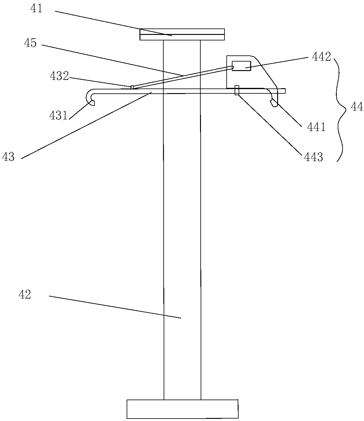
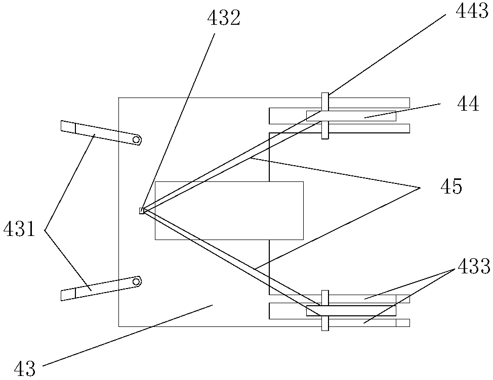
[0041] The clamp 4 structure of embodiment 3 is different from embodiment 1, see Figure 5 and Figure 6 , the first hook 431 and the conductive titanium plate 43 have an integrated structure, and the end of the conductive titanium plate 43 away from the first hook 431 has a long hole 434; the bottom of the fixed hook 44 has a sliding block 444, and the sliding block 444 has a sliding part 4441 and an anti-off part 4442, the length of the sliding part 4441 is less than the length of the elongated hole 434; the length of the anti-off part 4442 is adapted to the length of the elongated hole 434, just can pass through the elongated hole 434, and there is a rubber band fixing ring on the conductive titanium plate 43 432. This ensures that the anti-off part 4442 can pass through the elongated hole 434, and is not easy to fall off. Since there is a gap between the sliding part 4441 and the elongated hole 434, the fixed hook 44 can move in the elongated hole 434, and can be tightene...


PUM


Abstract

The invention belongs to the technical field of electroplating equipment, and particularly relates to an electroplating tank body automatic water inlet and water outlet mechanism and device. The mechanism comprises an ascending and descending assembly, a thrust assembly and a clamp, wherein the ascending and descending assembly comprises an ascending and descending motor, a rolling tube, an ascending and descending hanging belt, a fixing main rod, an ascending and descending transverse rod, a plurality of ascending and descending hanging plates and a main electric conduction rod; the pluralityof ascending and descending hanging plates are arranged and fixed on the ascending and descending transverse rod; the thrust assembly comprises a thrust motor, a gear, a rack, a hanging hook, a fixing frame, a thrust transverse rod and a plurality of thrust hanging rods; the thrust motor, the gear, the rack, the hanging hook, the fixing frame and the thrust transverse rod are fixed on the fixingmain rod; the plurality of thrust hanging rods are arranged and fixed on the thrust transverse rod; the clamp comprises a clamp installing block connected with the lower end of the main electric conduction rod and an electroplating electric conduction rod; the clamp installing block is rotationally connected with the thrust hanging rod. Tank-shaped products are driven to ascend and descend throughthe ascending and descending assembly; the thrust assembly drives the tank-shaped products to rotate; the automatic water inlet, water outlet and water pouring can be realized; meanwhile, a pluralityof tank-shaped products can be electroplated; the work intensity and the labor cost are greatly reduced; the production efficiency is improved.

Description

technical field [0001] The invention belongs to the technical field of electroplating equipment, and in particular relates to an automatic water inlet and outlet mechanism and device for an electroplating pot. Background technique [0002] Electroplated can-shaped products require conductive, degreasing, alkali cleaning, pickling, oxidation, water washing, drying and other processes. Due to the large demand, large diameter, and high height of the product, in the traditional production process, workers need to carry these individual can-shaped products through these process tanks, and each time they need to go through water entry, waiting, water discharge, and pouring. , conduction and other work, the work intensity is high, laborious and laborious, which increases the labor cost. And the working environment is often accompanied by acid or alkali gas and water vapor, etc., the temperature is high, and the operating environment of workers is very poor, which is harmful to the...

Claims


Application Information

Patent Timeline
IPC IPC(8): B66C25/00B66C1/10C25D17/00
CPCC25D17/00B66C1/10B66C25/00Y02P10/20
Inventor 马小勇
Owner 苏州南盛自动化科技有限公司
Why Eureka
Try Eureka