A multi-stage prefabricated track plate

A track slab and multi-stage technology, applied in the field of rail transit, can solve the problems of high cost of prefabricated molds, difficult precision control, low mold cycle utilization rate, etc., to reduce maintenance requirements and costs, reduce production costs, and increase cycle use rate effect

Inactive Publication Date: 2019-01-01
BEIJING JIUZHOUYIGUI SHOCK & VIBRATION ISOLATION
View PDF0 Cites 0 Cited by
  • Summary
  • Abstract
  • Description
  • Claims
  • Application Information

AI Technical Summary

Problems solved by technology

Because the track prefabricated parts are large-volume and large-tonnage parts, the following problems usually occur when most domestic track slabs are prefabricated in factories: (1) The cost of prefabricated molds is high, and the mold versatility is low
(2) Prefabricated molds require high stability and difficult precision control
(3) Problems such as long maintenance period and low mold cycle utilization rate indirectly affect the construction cost and construction progress of rail transit, etc.
In the current prefabrication of track slabs, the "top-down" pouring method is often adopted. The embedded casing for the rail part is located at the bottom of the mold, and the bottom of the track slab is located at the upper part of the mold. When the concrete is poured and vibrated, it will be skewed, which will lead to the failure of the normal installation of the fasteners; (2) the deformation of the track plate is large, resulting in the deviation of the position of the embedded casing; (3) the deformation during the use of the mold will lead to Part of the position that requires high-precision control is unqualified

Method used


Image

  • A multi-stage prefabricated track plate
  • A multi-stage prefabricated track plate
  • A multi-stage prefabricated track plate

Examples


Embodiment 2

[0045] This embodiment is basically the same as Embodiment 1. For the sake of brevity, in the description process of this embodiment, the same technical features as Embodiment 1 will not be described, and only the differences between this embodiment and Embodiment 1 will be described:

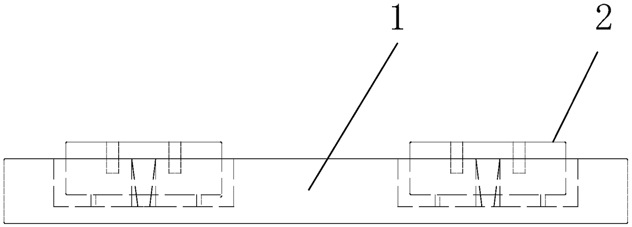
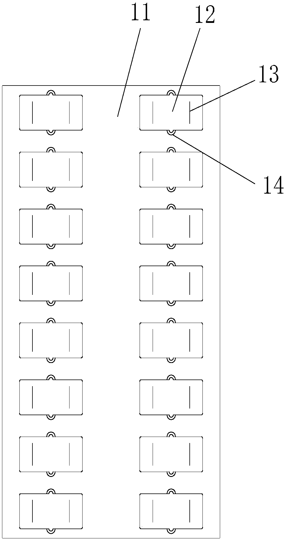
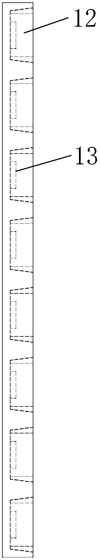
[0046] Such as Figure 8-14 As shown, in this embodiment, the number of reserved grooves 12 is multiple, and the plurality of reserved grooves 12 are distributed in a row along the longitudinal direction of the track on the lower plate 1, and at both ends of each block 21 respectively A pre-embedded casing 23 for installing rail fasteners is provided. Three grouting holes 14 are arranged on both sides of each reserved groove 12 . It should be noted that those skilled in the art should understand that in some other embodiments of the present invention, grouting holes 14 can also be provided on one side of the reserved groove 12, and in addition, the number of grouting holes 14 can also take oth...


PUM


Abstract

The invention relates to the technical field of rail transit and discloses a multi-stage prefabricated track plate. The track plate comprises a lower plate and a rail bearing block, the lower plate comprises a plate body and a reserved groove arranged on the plate body for accommodating the rail bearing block, and a first reserved rib is arranged at the bottom of the reserved groove; the rail bearing block comprises a block body, the bottom of the block body is provided with a second reserved bar connected with the first reserved bar, a pre-embedded sleeve for installing a rail fastener is arranged on the block body, and a grouting hole for pouring the rail bearing block and the lower plate together is also arranged on the lower plate. The multi-stage prefabricated rail plate provided by the invention is prefabricated by separating the lower plate and the rail bearing block, so that the production and manufacture of the multi-stage prefabricated rail plate is easy to be controlled, themould precision is low, and the cycle utilization rate and the universality of the mould for producing the rail plate are increased at the same time.

Description

technical field [0001] The invention relates to the technical field of rail transportation, in particular to a multi-stage prefabricated track slab. Background technique [0002] In recent years, rail transit has been vigorously developed in major cities in my country. According to different urban construction conditions and special needs, various types of rail structures have emerged as the times require. Due to the high construction precision requirements of the track structure, there are uncontrollable human factors in the on-site construction process, which leads to the substandard track structure and various diseases. [0003] At present, in the construction of urban rail transit in my country, it has become a new trend to prefabricate most important concrete structures in factories. Because the track prefabricated parts are large-volume and large-tonnage parts, the following problems usually occur when most domestic track slabs are prefabricated in factories: (1) The ...

Claims


Application Information

Patent Timeline
Patent Type & Authority Applications(China)
IPC IPC(8): E01B1/00
CPCE01B1/00
Inventor 房海元高淑华丁德云曾凡冲梁国君李腾任奇
Owner BEIJING JIUZHOUYIGUI SHOCK & VIBRATION ISOLATION
Why Eureka
Try Eureka