Concrete central protection fence
A technology for concrete and guardrails, applied to roads, road signs, traffic signals, etc., can solve the problems of complex structure, difficult maintenance and inconvenient installation of concrete central guardrails, and achieve the effect of simple structure, exquisite appearance and convenient installation
- Summary
- Abstract
- Description
- Claims
- Application Information
AI Technical Summary
Problems solved by technology
Method used
Image

Examples
Embodiment 1
[0020] As a preferred embodiment of the present invention, with reference to the attached figure 1 , this example discloses:
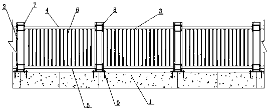
[0021] A concrete central guardrail, comprising a base 1, a column 2 and a guardrail 3, the base 1 is a base 1 made of concrete, and the columns 2 are arranged on the base 1 at intervals; the guardrail 3 includes an upper Cross bar 4, lower cross bar 5 and upright bar 6; The two ends of described upper cross bar 4 are respectively fixed on the upper ends of two adjacent columns 2, and the two ends of described lower cross bar 5 are respectively fixed on adjacent two upright columns 2 The lower end of the vertical bar 6 is arranged between the upper cross bar 4 and the lower cross bar 5, one end of the vertical bar 6 is fixed on the upper cross bar 4, and the other end is fixed on the lower cross bar 5.
Embodiment 2
[0023] As another preferred embodiment of the present invention, with reference to the attached figure 1 and 2 , this example discloses:
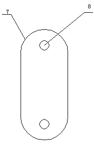
[0024] A concrete central guardrail, comprising a base 1, a column 2 and a guardrail 3, the base 1 is a base 1 made of concrete, and the columns 2 are arranged on the base 1 at intervals; the guardrail 3 includes an upper Cross bar 4, lower cross bar 5 and upright bar 6; The two ends of described upper cross bar 4 are respectively fixed on the upper ends of two adjacent columns 2, and the two ends of described lower cross bar 5 are respectively fixed on adjacent two upright columns 2 The lower end of the vertical rod 6 is arranged between the upper cross bar 4 and the lower cross bar 5, one end of the vertical rod 6 is fixed on the upper cross bar 4, and the other end is fixed on the lower cross bar 5; the upper cross bar 4 Both ends are provided with connecting plates 7, the connecting plates 7 are provided with mounting holes 8, the pos...
Embodiment 3
[0026] As another preferred embodiment of the present invention, with reference to the attached figure 1 and 2 , this example discloses:
[0027] In this embodiment, the two ends of the upper cross bar 4 are provided with a connecting plate 7, and the connecting plate 7 is provided with a mounting hole 8, and the position corresponding to the mounting hole 8 on the column 2 is provided with a through channel through the column 2. hole, one end of the upper cross bar 4 passes through the mounting hole 8 and the through hole through a screw and is fixed on the column 2; the two ends of the lower cross bar 5 are provided with a connecting plate 7, and the connecting plate 7 is provided with a mounting hole 8. A through hole through the column 2 is provided at the lower end of the column 2 corresponding to the installation hole 8, and one end of the lower cross bar 5 is fixed to the lower end of the column 2 through the installation hole 8 and the through hole through a screw; th...
PUM
 Abstract
Description
Claims
Application Information
 - R&D
- Intellectual Property
- Life Sciences
- Materials
- Tech Scout
- Unparalleled Data Quality
- Higher Quality Content
- 60% Fewer Hallucinations
Browse by: Latest US Patents, China's latest patents, Technical Efficacy Thesaurus, Application Domain, Technology Topic, Popular Technical Reports.
© 2025 PatSnap. All rights reserved.Legal|Privacy policy|Modern Slavery Act Transparency Statement|Sitemap|About US| Contact US: help@patsnap.com