Detonation control method for reducing blast vibration

A control method and blasting vibration technology, which is applied in the field of blasting, can solve problems such as slow construction progress, difficulty in undertaking large-scale blasting projects, and low reliability of blasting transmission networks, so as to speed up blasting construction progress and reduce blasting vibration effects , Improve the effect of blasting quality

Inactive Publication Date: 2019-01-01
CHANGAN UNIV +1
View PDF4 Cites 12 Cited by
  • Summary
  • Abstract
  • Description
  • Claims
  • Application Information

AI Technical Summary

Problems solved by technology

In the prior art, in order to control the seismic effect or vibration effect of blasting, millisecond delay detonation technology hole by hole has been widely used in open-pit blasting at home and abroad. In addition to minimizing the need for single-stage detonation, the shock reduction principle of this technology is It is also the purpose of using a short delay interval to make the seismic signals of each section interfere with each other and reduce vibration. However, in practical applications, due to the problem of the detonation accuracy of industrial detonators, in order to avoid the superposition of blasting vibrations caused by the detonator jumping section The phenomenon that the effect increases often increases the delay interval time, which is not conducive to the further shortening of the millisecond delay
[0003] In addition, rock foundation pit excavation projects of infrastructure projects often require deep-hole blasting construction in complex surrounding environments, and it is necessary to ensure the safety of surrounding buildings. The reliability of the existing blast transmission network is low, and it is difficult to undertake such Large-scale blasting works, slowing down the construction progress

Method used


Image

  • Detonation control method for reducing blast vibration
  • Detonation control method for reducing blast vibration
  • Detonation control method for reducing blast vibration

Examples


Embodiment Construction

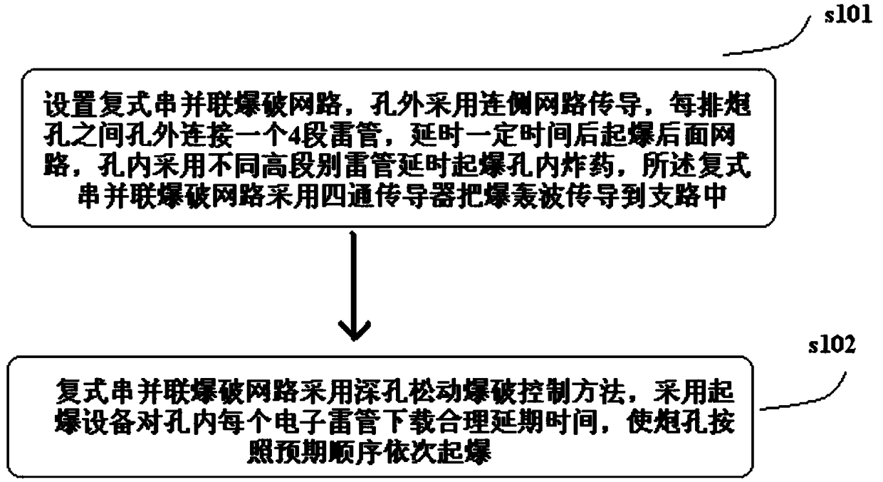
[0024] see figure 1 , the detonation control method for reducing blasting vibration includes steps:

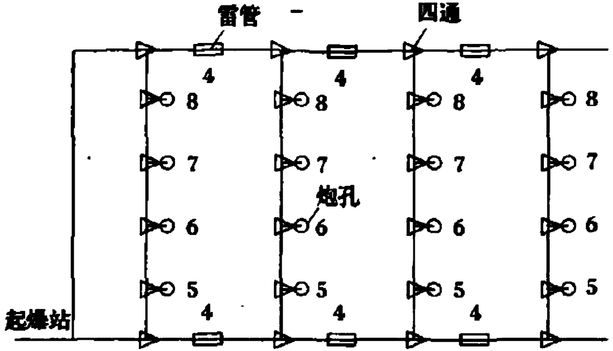
[0025] S101, setting up a duplex series-parallel blasting network, see figure 2 , the side network conduction is used outside the hole, and a 4-stage detonator is connected outside the hole between each row of blastholes, and the rear network is detonated after a certain period of time. The compound series-parallel blasting network uses a four-way conductor to conduct the detonation wave into the branch;

[0026] S102, the compound series-parallel blasting network adopts the deep hole loosening blasting control method, and uses the blasting equipment to set a reasonable delay time for each electronic detonator in the hole, so that the blast holes are detonated in sequence according to the expected sequence.

[0027] figure 2 The blasting network is designed to better control the hazards of blasting vibration, ensure the safety of buildings, reduce the amount of single-sta...


PUM


Abstract

The invention provides a detonation control method for reducing blast vibration. The detonation control method for reducing blast vibration comprises the steps of (1) setting a compound series-parallel blasting network, adopting a connected side network for conducting outside holes, connecting a 4-section detonator outside holes between each row of blast holes, detonating a back network after delaying for a certain time, adopting detonators with different high sections for delaying to detonate explosives in the blast holes, and enabling the compound series-parallel blasting network to adopt afour-way conductor for conducting a detonation wave into a branch circuit; and (2) enabling the compound series-parallel blasting network to adopt a long hole loose blasting control method, adopting detonation equipment for downloading reasonable delay time for each electronic detonator in each hole, and sequentially detonating the blast holes according to the expected sequence. According to the method, the blasting quality can be improved, the blasting vibration effect is reduced, the one-time blasting scale is expanded, and the reliability of the high-precision millisecond nonel detonators and millisecond delay blasting networks inside and outside the holes can be improved, so that the large-scale blasting can be realized, and the blasting construction progress is accelerated.

Description

technical field [0001] The invention relates to an initiation control method for reducing the blasting vibration effect, which belongs to the field of blasting technology, in particular to a technology capable of effectively reducing the blasting vibration effect. Background technique [0002] While blasting greatly promotes the development of productivity, it is also accompanied by harmful effects such as vibration, air shock waves and other harmful effects caused by blasting. In the prior art, in order to control the seismic effect or vibration effect of blasting, millisecond delay detonation technology hole by hole has been widely used in open-pit blasting at home and abroad. In addition to minimizing the need for single-stage detonation, the shock reduction principle of this technology is It is also the purpose of using a short delay interval to make the seismic signals of each section interfere with each other and reduce vibration. However, in practical applications, du...

Claims


Application Information

Patent Timeline
Patent Type & Authority Applications(China)
IPC IPC(8): F42D1/05F42D3/04F42D5/045
CPCF42D1/05F42D3/04F42D5/045
Inventor 陈能远南亚林行增奇徐唯田理嘉牛利刚
Owner CHANGAN UNIV
Why Eureka
Try Eureka