Eureka AIR delivers breakthrough ideas for toughest innovation challenges, trusted by R&D personnel around the world.

Direct-current contactor

A DC contactor and dynamic contact technology, applied in the direction of relays, electromagnetic relays, detailed information of electromagnetic relays, etc., can solve the problems of low energy saving and high coil power consumption, and achieve the effects of convenient installation, low production cost, and reduced startup power consumption

Pending Publication Date: 2019-01-01
昆山国力源通新能源科技有限公司
View PDF0 Cites 0 Cited by
  • Summary
  • Abstract
  • Description
  • Claims
  • Application Information

AI Technical Summary

Problems solved by technology

[0003] However, the existing DC contactor structure usually makes the power consumption of the coil too high, not energy-saving

Method used


Image

  • Direct-current contactor
  • Direct-current contactor
  • Direct-current contactor

Examples


Embodiment 1

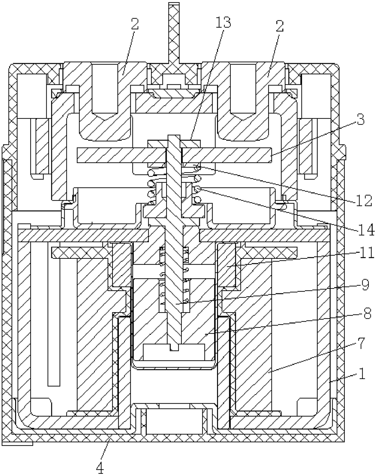
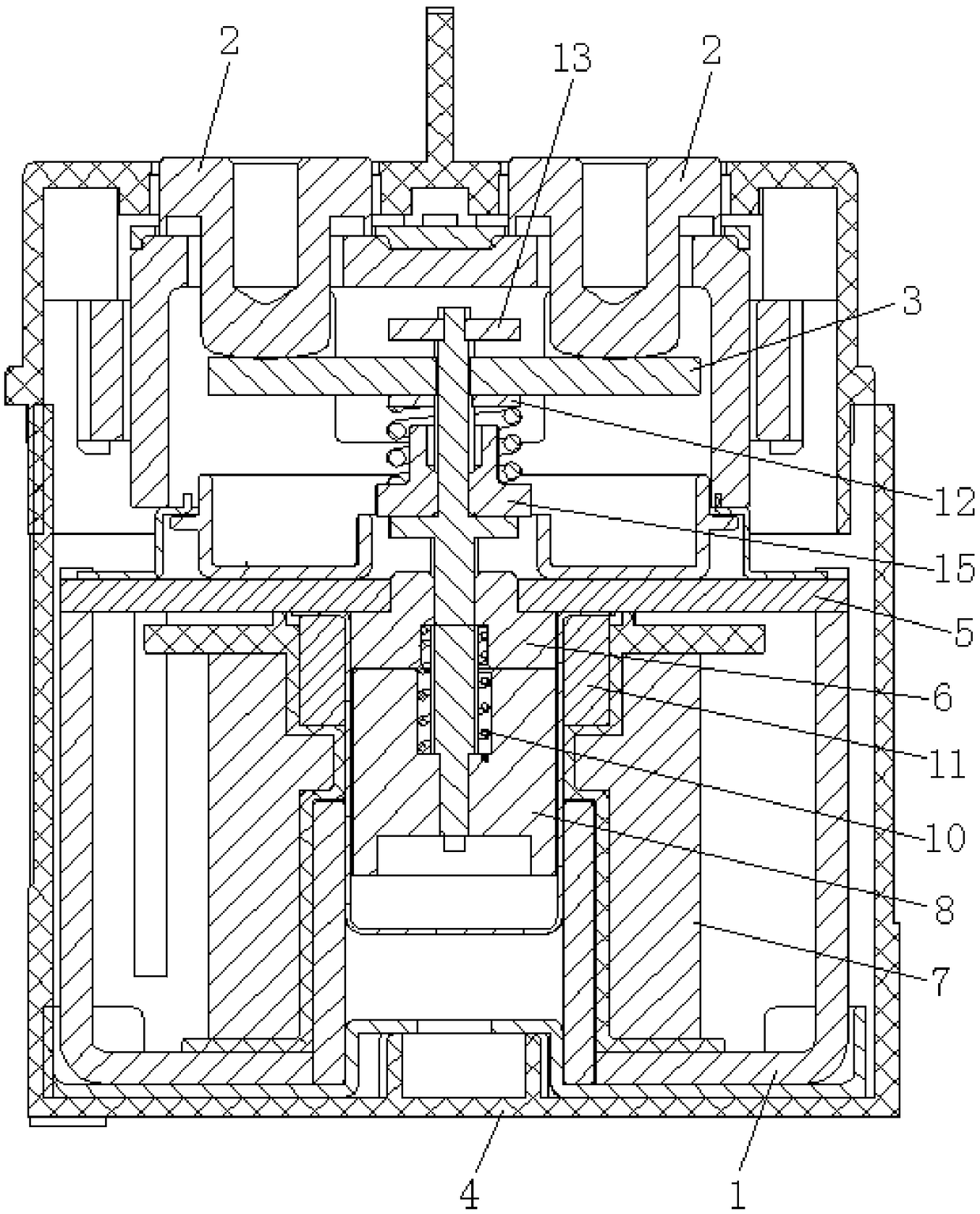
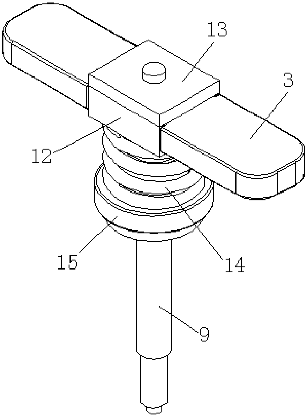
[0032] Please refer to the attached figure 1 And attached figure 2 As shown, they are schematic cross-sectional structural diagrams of the DC contactor in the present invention in the disconnected working state and the connected working state; the DC contactor includes a housing 1, two static contacts 2, a moving contact piece 3 and a driving mechanism, Wherein, an insulating shell 4 is fixedly sheathed outside the housing 1, and a diaphragm 5 is positioned and installed in the inner cavity of the housing 1, and the diaphragm 5 divides the inner cavity of the housing 1 Separated into an upper chamber and a lower chamber, and a static iron core 6 is positioned and installed on the diaphragm 5; the two static contacts 2 are arranged side by side in the upper chamber, and the moving contact piece 3 is also arranged in the upper chamber, and the moving contact piece 3 is arranged vertically opposite to the two static contacts 2 respectively; the driving mechanism has a coil 7, a...


PUM


Abstract

The invention discloses a direct-current contactor. The direct-current contactor comprises a housing, two fixed contacts, a movable contact sheet and a driving mechanism; a transverse partition plateis installed in the inner cavity of the housing in a positioned manner; the transverse partition plate divides the inner cavity of the housing into an upper chamber and a lower chamber; the transversepartition plate is provided with a fixed iron core in a positioned manner; the fixed contacts are disposed side by side in the upper chamber; the movable contact sheet is disposed in the upper chamber and is opposite to the two fixed contacts along a vertical direction; the driving mechanism is provided with a coil, a movable iron core and a push rod; the coil is positioned in the lower chamber;the movable iron core is arranged in a space enclosed by the coil; the lower end of the push rod passes through the movable iron core in a close-fit manner; the upper part of the push rod moveably passes through the fixed iron core and then is connected with the movable contact sheet; a lap of recessed mounting groove is formed in the inner side wall of the support of the coil; a permanent magnetring is positioned and embedded in the mounting groove; and with the permanent magnet ring adopted, the power consumption of the coil can be effectively reduced, and the energy-saving performance of the direct-current contactor can be greatly improved.

Description

technical field [0001] The invention relates to the technical field of DC contactors, and specifically provides a DC contactor capable of reducing coil power consumption. Background technique [0002] The conventional structure of DC contactors currently on the market is: including a housing, two static contacts, a moving contact piece and a drive mechanism, wherein an insulating shell is fixedly sleeved outside the housing, and an insulating shell is fixed in the inner cavity of the housing. A transverse partition is installed in the middle, and the inner cavity of the housing is divided into an upper chamber and a lower chamber by the transverse partition, and a static iron core is also positioned and installed on the transverse partition; the two described The static contacts are arranged side by side in the upper chamber, the moving contact piece is also arranged in the upper chamber, and the moving contact piece is vertically opposite to the two static contacts; The dr...

Claims


Application Information

Patent Timeline
Patent Type & Authority Applications(China)
IPC IPC(8): H01H50/44H01H50/54
CPCH01H50/44H01H50/54
Inventor 杨泉良王琪吴芳顾春朋文艳慧
Owner 昆山国力源通新能源科技有限公司
Why Eureka
Eureka Blog
Learn More