LED energy-saving driving system based on overvoltage protection circuit

An overvoltage protection circuit and drive system technology, applied in emergency protection circuit devices, overvoltage-responsive protection, circuit devices, etc., can solve problems such as inability to meet energy-saving requirements and high power consumption, and achieve reduced startup power consumption , The starting current is small, and the effect of avoiding damage

Inactive Publication Date: 2016-10-12
CHENGDU SINOMETALLURGY ENERGY CONSERVATION ENVIRONMENTAL PROTECTION ENG CO LTD
0 Cites 0 Cited by

AI-Extracted Technical Summary

Problems solved by technology

However, the traditional LED drive system consumes a lot of po...

Method used

[0028] The present invention adopts GR6953 integrated chip as the control chip and in combination with peripheral circuits, so that the present invention forms a half-bridge control structure, thereby reducing the startup power consumption of the present i...

Abstract

The invention discloses an LED energy-saving driving system based on an overvoltage protection circuit. The LED energy-saving driving system is characterized by manly consisting of a transformer T, a control chip U2, a power supply circuit and a frequency adjustment circuit which are connected with the control chip U2, a diode D4 which has a P pole connected with the frequency adjustment circuit and an N pole connected with a VS pin of the control chip U2, and the like. The system, by use of a GR6953 integrated chip as the control chip and through combination with a peripheral circuit, forms a half-bridge control structure, such that starting power consumption is reduced, and the system is more energy-saving. At the same time, the circuit can be automatically disconnected in case of overvoltages, the system itself and LEDs are prevented from damage caused by the overvoltages.

Application Domain

Electroluminescent light sourcesSemiconductor lamp usage +1

Technology Topic

Image

  • LED energy-saving driving system based on overvoltage protection circuit
  • LED energy-saving driving system based on overvoltage protection circuit

Examples

  • Experimental program(1)

Example Embodiment

[0016] Example
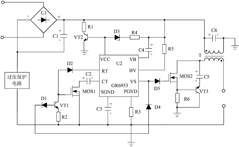
[0017] Such as figure 1 As shown, the present invention mainly consists of a control chip U2, a transformer T, a power supply circuit and a frequency adjustment circuit respectively connected to the control chip U2, the P pole is connected to the frequency adjustment circuit, and the N pole is connected to the VS pin of the control chip U2 The diode D4, the anode is connected to the SGND pin of the control chip U2, the cathode is connected to the capacitor C3 of the frequency adjustment circuit, one end is connected to the PGND pin of the control chip U2, and the other end is connected to the frequency adjustment circuit while being grounded The resistor R3 is connected in series to the gate drive circuit between the VS pin of the control chip U2 and the non-identical end of the secondary inductor coil of the transformer T, and the overvoltage protection circuit is connected in series between the power supply circuit and the frequency adjustment circuit , And a capacitor C6 whose positive pole is connected to the same-named end of the primary inductance coil of the transformer T, and the negative pole is connected to the non-identical end of the primary inductance coil of the transformer T. The same-named end of the primary inductor coil of the transformer T is connected to the power circuit. In order to achieve the purpose of the present invention, the control chip U2 is preferably implemented by a GR6953 integrated chip.
[0018] Wherein, the power supply circuit is composed of a diode rectifier U1, a transistor VT2, a resistor R1, a resistor R4, a resistor R5, a capacitor C1, a Zener diode D3 and a capacitor C4.
[0019] When connected, the anode of the capacitor C1 is connected to the anode output end of the diode rectifier U1, and its cathode is connected to the cathode output end of the diode rectifier U1. The resistor R1 is connected in series between the anode of the capacitor C1 and the collector of the transistor VT2. The P pole of the Zener diode D3 is connected to the base of the transistor VT2, and its N pole is connected to the anode of the capacitor C1 through the resistor R4. The resistor R5 is connected in series between the positive pole of the capacitor C1 and the HV pin of the control chip U2. The positive electrode of the capacitor C4 is connected to the positive electrode of the capacitor C1, and the negative electrode is connected to the VB pin of the control chip U2.
[0020] At the same time, the emitter of the transistor VT2 is grounded, and its base is connected to the VCC pin of the control chip U2. The positive pole of the capacitor C1 is also connected to the end of the same name of the primary inductor coil of the transformer T. The negative output terminal of the diode rectifier U1 is connected to the input terminal of the overvoltage protection circuit. The input end of the diode rectifier U1 is connected to the power supply.
[0021] The frequency adjustment circuit is composed of a transistor VT1, a field effect transistor MOS1, a resistor R2, a diode D1, a diode D2 and a capacitor C2.
[0022] When connecting, the N pole of the diode D1 is connected to the P pole of the diode D4, and the P pole is connected to the base of the transistor VT1. The resistor R2 is connected in series between the emitter of the transistor VT1 and the source of the field effect transistor MOS1. The P pole of the diode D2 is connected with the collector of the triode VT1, and its N pole is connected with the RT pin of the control chip U2. The positive pole of the capacitor C2 is connected with the drain of the field effect transistor MOS1, and the negative pole is connected with the CT pin of the control chip U2.
[0023] The source of the field effect transistor MOS1 is connected with the output end of the overvoltage protection circuit, and its gate is connected with the collector of the triode VT1. The cathode of the capacitor C3 is connected to the source of the field effect transistor MOS1. The source of the field effect tube MOS1 and the end of the same name of the secondary inductance coil of the transformer T jointly form an output end and are connected to the LED lamp.
[0024] In addition, the gate drive circuit is composed of a field effect transistor MOS2, a transistor VT3, a diode D5, a resistor R6 and a capacitor C5.
[0025] When connected, the P pole of the diode D5 is connected to the VS pin of the control chip U2, and its N pole is connected to the gate of the field effect transistor MOS2. The resistor R6 is connected in series between the source of the field effect transistor MOS2 and the collector of the triode VT3. The negative pole of the capacitor C5 is connected to the emitter of the transistor VT3, and its positive pole is connected to the non-identical end of the secondary inductor coil of the transformer T. The drain of the field effect transistor MOS2 is connected to the anode of the capacitor C5. The base of the triode VT3 is connected with the source of the field effect transistor MOS2, and the collector is grounded.
[0026] Such as figure 2 As shown, the overvoltage protection circuit is composed of a transistor VT4, a bidirectional thyristor D8, a resistor R7, a resistor R8, a resistor R9, a resistor R10, a resistor R11, a capacitor C7, a capacitor C8, a capacitor C9, a diode D6, and a diode D7.
[0027] When connected, the cathode of the capacitor C7 is connected to the P pole of the diode D7, and its anode is used as the input end of the overvoltage protection circuit and is connected to the cathode output end of the diode rectifier U1. The N pole of the diode D7 is connected to the first anode of the bidirectional thyristor D8. The N pole of the diode D6 is connected to the cathode of the capacitor C7, and the P pole is grounded. The anode of the capacitor C8 is connected to the first anode of the bidirectional thyristor D8, and the cathode of the capacitor C8 is connected to the P pole of the diode D6 after the resistor R7. The resistor R8 is connected in series between the control terminal of the bidirectional thyristor D8 and the collector of the triode VT4. One end of the resistor R10 is connected to the second anode of the bidirectional thyristor D8, and the other end is connected to the emitter of the triode VT4 through the resistor R9. The positive electrode of the capacitor C9 is connected to the collector of the triode VT4, and its negative electrode is connected to the second anode of the bidirectional thyristor D8 through the resistor R11. At the same time, the connection point of the resistor R9 and the resistor R10 is grounded; the second anode of the bidirectional thyristor D8 serves as the output terminal of the overvoltage protection circuit and is connected to the source of the field effect transistor MOS1.
[0028] The invention uses the GR6953 integrated chip as the control chip and combines with the peripheral circuit, so that the invention forms a half-bridge control structure, thereby reducing the startup power consumption of the invention and making the invention more energy-saving. At the same time, the present invention can automatically disconnect the circuit when an overvoltage occurs, so as to prevent the system itself and the LED from being damaged by the overvoltage.

PUM

no PUM

Description & Claims & Application Information

We can also present the details of the Description, Claims and Application information to help users get a comprehensive understanding of the technical details of the patent, such as background art, summary of invention, brief description of drawings, description of embodiments, and other original content. On the other hand, users can also determine the specific scope of protection of the technology through the list of claims; as well as understand the changes in the life cycle of the technology with the presentation of the patent timeline. Login to view more.

Similar technology patents

Classification and recommendation of technical efficacy words

  • Reduce startup power consumption
  • Small starting current

Overvoltage protective LED energy-saving driving system based on power amplification circuit

Owner:CHENGDU SINOMETALLURGY ENERGY CONSERVATION ENVIRONMENTAL PROTECTION ENG CO LTD

LED energy-saving driving system

Owner:CHENGDU SINOMETALLURGY ENERGY CONSERVATION ENVIRONMENTAL PROTECTION ENG CO LTD

Control method of electronic expansion valve of air conditioner

InactiveCN104197465ALow starting resistanceSmall starting currentSpace heating and ventilation safety systemsSpace heating and ventilation control systemsSystem elementCapacitance
Owner:WUHU MATY AIR CONDITIONING EQUIP CO LTD

Method for providing given frequency in motor starting phase

InactiveCN101860286ASmooth startSmall starting currentPolyphase induction motor starterPower gridMutation
Owner:CHINA CNR LIMITED DALIAN ELECTRIC TRACTION R&D CENT
Why Eureka
Try Eureka