
Dispersed-speed flexible motor

A flexible and speed-dissipating technology, applied in the direction of electromechanical devices, electrical components, mechanical equipment, etc., can solve the problems of lack of speed, low power factor, large wasteful power loss, etc., to reduce startup power consumption and transmission power consumption, reduce Starting and running conditions, the effect of meeting the needs of use

Pending Publication Date: 2021-08-27
WEIHAI TUANZHONG TRANSMISSION CO LTD
View PDF0 Cites 0 Cited by
  • Summary
  • Abstract
  • Description
  • Claims
  • Application Information

AI Technical Summary

Problems solved by technology

[0004] Therefore, the traditional motor has the following application deficiencies. First, the more the number of poles, the lower the energy efficiency; second, the more the number of poles, the lower the power factor and the greater the loss of idle power; the third is that it cannot provide the required speed in a wide range, such as at 50Hz power frequency Under certain conditions, a motor with a synchronous speed of 900r / min is required, or many specific speeds such as a synchronous speed of 5000r / min are required. According to the speed relationship corresponding to the number of motor poles, it is impossible to flexibly provide motor speeds with different needs.
[0005] The existing electric control technology such as frequency conversion technology applied to the motor can solve the problem of different speeds of the motor, but the electric control technology itself needs energy consumption, which is not conducive to energy saving and emission reduction for long-term running equipment
The existing matching traditional motor has high gear transmission efficiency and can provide the speed required by various specific working conditions, but it cannot realize flexible transmission, and it is difficult to deal with startup and load overload.
At the same time, the type selection design of the equipped motor cannot be selected according to the rated working conditions. The super-power motor selection of the large horse-drawn trolley is only for the start-up and the anti-environmental ability of the overload condition, resulting in high energy consumption and cannot adapt to modern Requirements for energy saving and consumption reduction
The patent applications with patent publication numbers CN2021103236139, CN2021103235598, CN2021103234928 and CN2021103235579 disclose four kinds of flexible motors and flexible starting methods. Selection requirements, and maintain high-efficiency operation under rated working conditions, but do not have the speed required for various specific working conditions, which restricts many application requirements for flexible motors that require different output speeds

Method used


Image

  • Dispersed-speed flexible motor
  • Dispersed-speed flexible motor
  • Dispersed-speed flexible motor

Examples


Embodiment 1

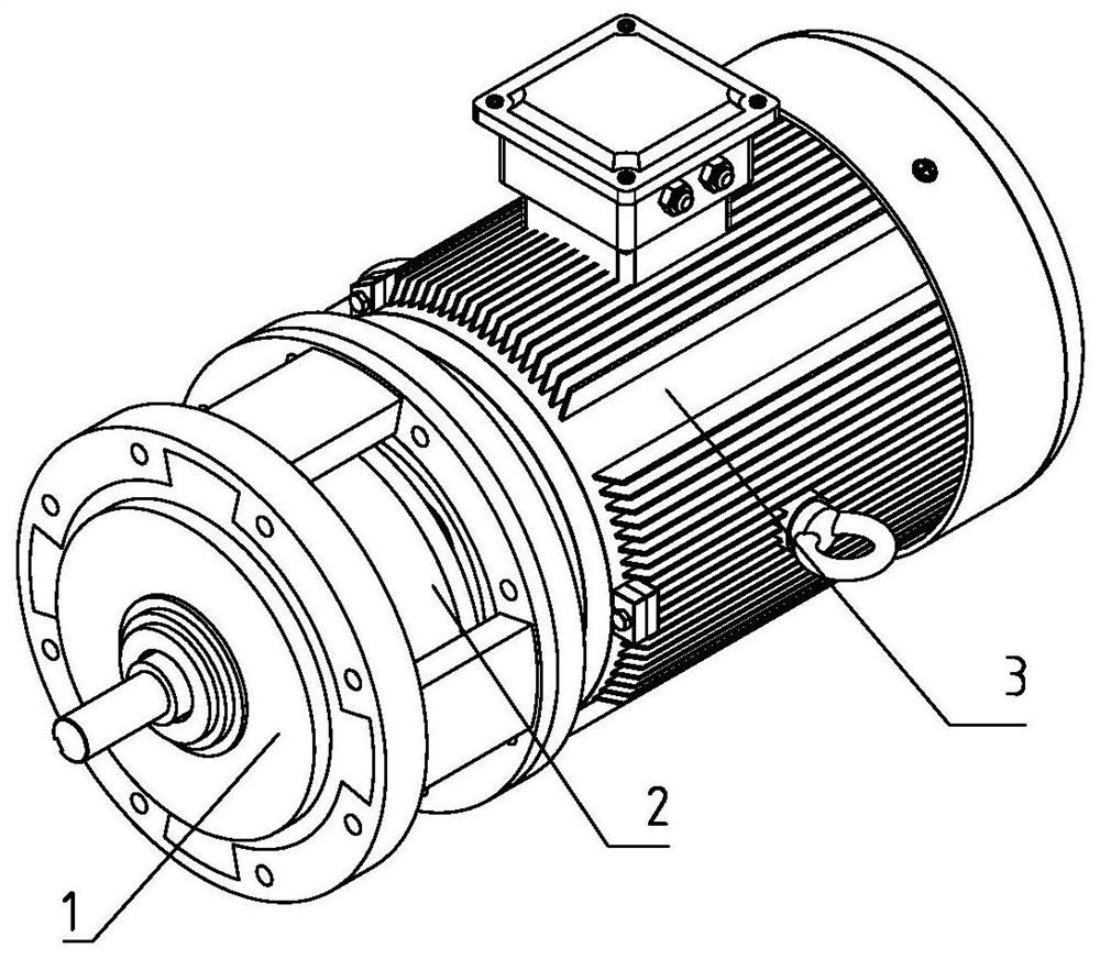
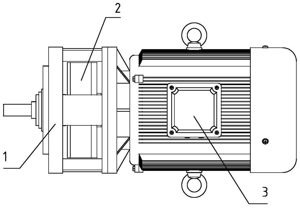
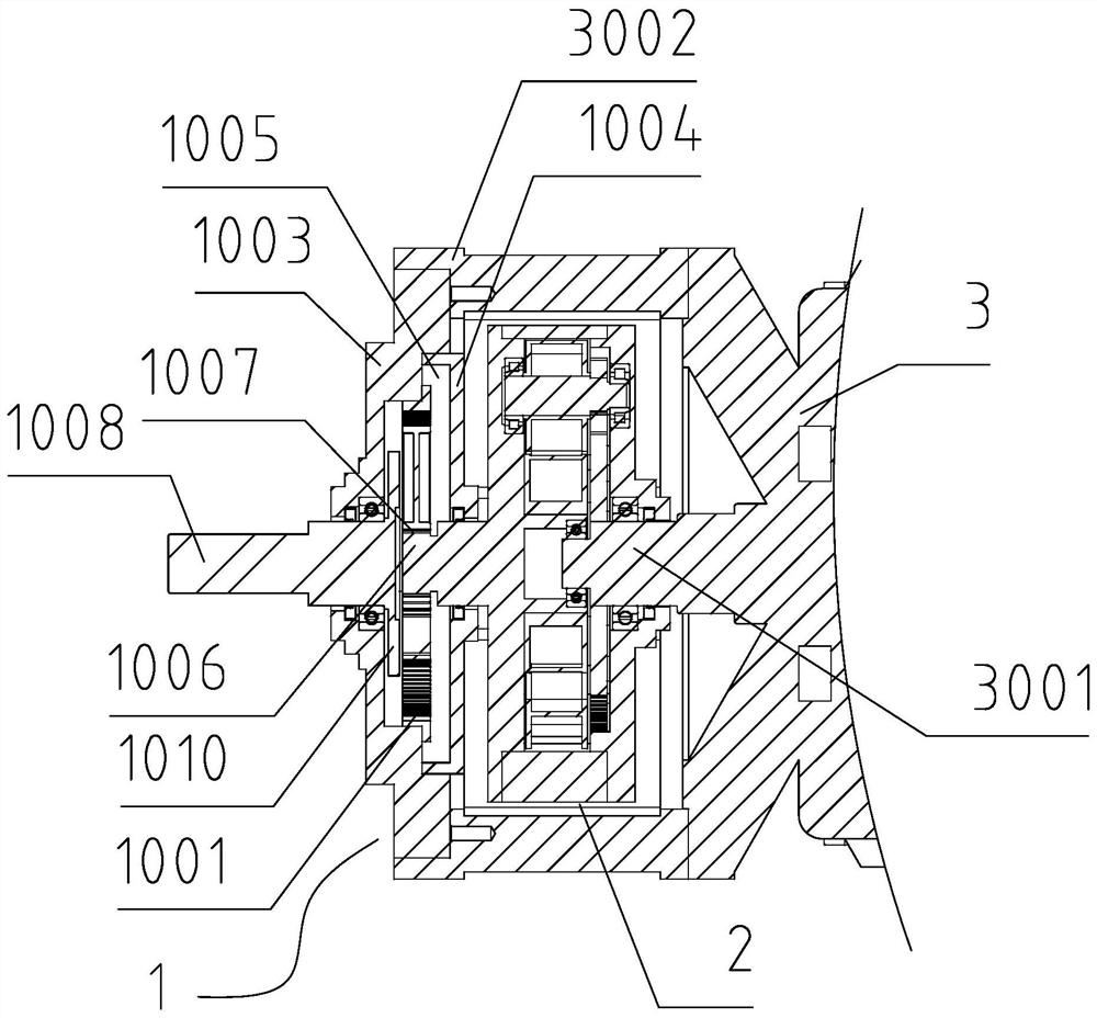
[0046] Figure 1-Figure 10 as well as Figure 17-Figure 20 It is an embodiment of a loose-speed flexible motor of the present invention. It can be seen in the figure that it includes a motor body 3, a continuously variable transmission 2 and a reducer 1. The front end of the motor body 3 is fixed with a mounting seat 3002, and the motor body The front end of 3 is rotated with a motor rotor output shaft 3001, the inside of the mounting base 3002 is provided with a continuously variable transmission 2, the outside of the mounting base 3002 is fixedly connected with the reducer 1, and one end of the continuously variable transmission 2 is connected with the motor rotor output shaft 3001, The other end of the continuously variable transmission 2 is provided with an intermediate transmission shaft 1006, and the continuously variable transmission 2 is rotationally connected with the reducer 1 through the intermediate transmission shaft 1006; the reducer 1 includes a reducer housing ...

Embodiment 2

[0058] Figure 11-Figure 20 It is another embodiment of a loose-speed flexible motor of the present invention. As can be seen in the figure, a loose-speed flexible motor includes a motor main body 3, a continuously variable transmission 2 and a reducer 1, and the front end of the motor main body 3 is fixed. There is a mounting base 3002, the front end of the motor main body 3 rotates and is provided with a motor rotor output shaft 3001, the inside of the mounting base 3002 is provided with a continuously variable transmission 2, the outside of the mounting base 3002 is fixedly connected with the reducer 1, and one end of the continuously variable transmission 2 is connected to the The motor rotor output shaft 3001 is connected, and the other end of the continuously variable transmission 2 is provided with an intermediate transmission shaft 1006, and the continuously variable transmission 2 is rotationally connected with the reducer 1 through the intermediate transmission shaft ...


PUM


Abstract

The invention provides a dispersed-speed flexible motor comprising a motor main body, a stepless speed transmission and a speed reducer, wherein the front end of the motor main body is fixedly provided with a mounting seat, the front end of the motor main body is rotationally provided with a motor rotor output shaft, the stepless speed transmission is arranged in the mounting seat, and the outer side of the mounting seat is fixedly connected with the speed reducer. One end of the stepless speed transmission is connected with a motor rotor output shaft, the other end of the stepless speed transmission is provided with an intermediate transmission shaft, and the stepless speed transmission is rotationally connected with the speed reducer through the intermediate transmission shaft. The dispersed-speed flexible motor has the whole-process flexible transmission performance, the dispersed-speed flexible motor can adaptively isolate the load in the starting process, light-load starting is achieved during starting, an additional starting control device does not need to be added, and the transmission mode can be adaptively adjusted according to the change of the load in the running process. The dispersed-speed flexible motor can be widely applied to type selection of motors in various transmission fields, and can provide various dispersed speed outputs.

Description

technical field [0001] The invention relates to a motor, in particular to a loose-speed flexible motor. Background technique [0002] With the goal of carbon peaking and carbon neutrality becoming the consensus of China and the world, energy saving and emission reduction is not only of economic significance, but more importantly, it is of great significance to prevent the global temperature rise. For the motor industry, which uses the largest electric energy, energy saving and emission reduction row is especially important. [0003] The number of poles of a traditional motor is the number of magnetic poles of the motor, such as a 2-pole motor and a 4-pole motor. The number of poles corresponds to the synchronous speed of the motor. The synchronous speed of the pole motor is 1000r / min, the synchronous speed of the 8-pole motor is 750r / min, the synchronous speed of the 10-pole motor is 600r / min, and the synchronous speed of the 12-pole motor is 500r / min. Usually, motors with...

Claims


Application Information

Patent Timeline
Patent Type & Authority Applications(China)
IPC IPC(8): F16H1/32F16H3/70F16H57/023F16H57/028F16H57/031F16H57/08F16H61/66H02K7/10H02K7/116
CPCF16H1/32F16H3/70F16H57/023F16H57/028F16H57/031F16H57/082F16H61/66F16H2001/327H02K7/10H02K7/116
Inventor 唐玉凝唐永峰唐沛宇刘涛
Owner WEIHAI TUANZHONG TRANSMISSION CO LTD
Learn More