multi-frequency antenna device

A multi-frequency antenna and resonant frequency technology, applied in the field of multi-frequency antenna devices, can solve the problems of reducing the resonant frequency of the microstrip antenna 10, increasing the manufacturing cost of the microstrip antenna 10, and being difficult to adjust accurately and effectively at the same time.

Active Publication Date: 2020-11-06
UNICTRON TECH CORP
View PDF6 Cites 0 Cited by
  • Summary
  • Abstract
  • Description
  • Claims
  • Application Information

AI Technical Summary

Problems solved by technology

Of course, an insulating substrate 11 with a higher dielectric coefficient can also be used to make the microstrip antenna 10 to achieve the purpose of reducing the resonance frequency of the microstrip antenna 10. Although this method can avoid increasing the volume of the microstrip antenna 10, it will also increase the volume of the microstrip antenna 10. Manufacturing cost of microstrip antenna 10
When the size and dielectric coefficient of the insulating substrate are selected, basically, the resonant frequency that can be formed on the microstrip antenna has been fixed. Therefore, when making a microstrip antenna with two resonant frequencies on an insulating substrate , it is not easy to adjust the two resonant frequencies accurately and effectively at the same time

Method used


Image

  • multi-frequency antenna device
  • multi-frequency antenna device
  • multi-frequency antenna device

Examples


Embodiment Construction

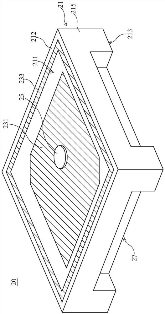
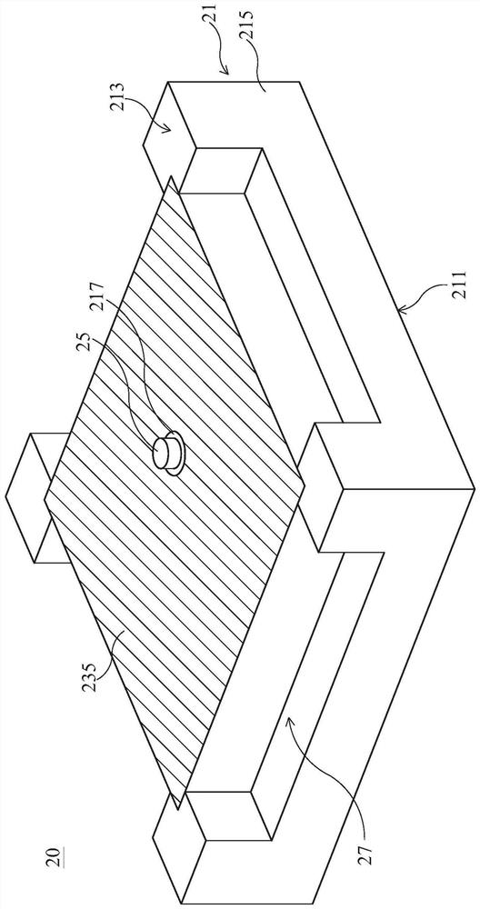
[0092] see figure 2 and image 3 , are respectively the top and bottom perspective schematic diagrams of an embodiment of the multi-frequency antenna device of the present invention. As shown in the figure, the multi-frequency antenna device 20 mainly includes an insulating base 21, at least one first electrode layer 231, at least one second electrode layer 233, at least one third electrode layer 235, at least one conductive element 25 and at least one concave Slot 27.

[0093] The insulating base 21 includes a first surface 211, a second surface 213, at least one side surface 215 and at least one first through hole 217, wherein the first surface 211 and the second surface 213 are two opposing sides across the insulating base 21. The surfaces, for example the first surface 211 is the top surface and the second surface 213 is the bottom surface. In addition, the first surface 211 is connected to the second surface 213 via the side surface 215 , for example, the insulating b...


PUM


Abstract

The utility model discloses a multi -frequency antenna device sets up an at least first electrode layer and an at least the second electrode lay on an insulating body's first surface, the second electrode lay lies in the periphery on first electrode layer. Set up an at least the third electrode layer on insulating body's second surface, the first surface is separating two surfaces that this insulating body is relative with the second surface. A conductive element pierces through insulating body to connect the first electrode layer. An at least recess setting overlaps with the second electrodelay totally or partially in the projection of first surface at insulating body's side surface and / or second surface, recess. The first electrode layer can form different resonance frequency with thesecond electrode lay, and the setting through the recess can change the effective dielectric constant between the second electrode lay and the third electrode layer to the produced resonance frequency of adjustment the second electrode lay.

Description

technical field [0001] The invention relates to a multi-frequency antenna device. Background technique [0002] Compared with ordinary antennas, the microstrip antenna structure can be used to make circularly polarized antennas. It has the advantages of planar structure, mass production, and easy integration in active components or circuit boards. Therefore, it is widely used in various wireless transmission On the device, such as GPS (Global Positioning System) or radio frequency identification (RFID). [0003] see figure 1 , is a perspective view of the used microstrip antenna. As shown in the figure, the used microstrip antenna 10 includes an insulating substrate 11, a first conductive layer 13, a second conductive layer 15 and a conductive element 171, wherein the first conductive layer 13 is located on the upper surface of the insulating substrate 11 , while the second conductive layer 15 is located on the lower surface of the insulating base 11 . The conductive ele...

Claims


Application Information

Patent Timeline
Patent Type & Authority Patents(China)
IPC IPC(8): H01Q1/38
CPCH01Q1/38
Inventor 周志伸叶宗寿杨翔程吕清霖
Owner UNICTRON TECH CORP
Why Eureka
Try Eureka