
Array antenna beam adjustment device and array antenna with adjustable beam width

A technology of array antenna and adjustment device, which is applied in the direction of antenna support/installation device, antenna, antenna array, etc., and can solve the problems of affecting the input oscillator impedance, affecting the working bandwidth of the oscillator, and the difficulty of realizing ultra-wideband antennas.

Pending Publication Date: 2019-01-01
南京澳博阳射频技术有限公司
View PDF0 Cites 4 Cited by
  • Summary
  • Abstract
  • Description
  • Claims
  • Application Information

AI Technical Summary

Problems solved by technology

[0004] First, changing the form of the oscillator will affect the impedance of the input oscillator, which in turn affects the working bandwidth of the oscillator, making it difficult to design an ultra-wideband antenna;
[0005] Second, for multi-frequency antennas, the vibrators in different frequency bands need to share the reflector. If the height of the vibrator in a certain frequency band is changed from the reflector, it will affect the radiation beam shape of the vibrators in other frequency bands;
[0006] Third, changing the shape of the reflector can only change the radiation pattern of a small frequency of interest. The widening or narrowing of the beam width cannot be realized in an ultra-wideband array

Method used


Image

  • Array antenna beam adjustment device and array antenna with adjustable beam width
  • Array antenna beam adjustment device and array antenna with adjustable beam width
  • Array antenna beam adjustment device and array antenna with adjustable beam width

Examples


Embodiment Construction

[0032] In order to make the purpose, technical solutions and advantages of the embodiments of the present invention clearer, the technical solutions of the present invention will be clearly and completely described below in conjunction with the accompanying drawings. Obviously, the described embodiments are part of the embodiments of the present invention, not all of them. the embodiment. Based on the embodiments of the present invention, all other embodiments obtained by persons of ordinary skill in the art without making creative efforts belong to the protection scope of the present invention.

[0033] At present, the existing methods for changing the lobe width of the oscillator radiation beam include: changing the form of the oscillator, such as the half-wave oscillator radiation beam width, the full-wave oscillator radiation beam is narrow, and the unit that is larger than the half-wave oscillator and smaller than the full-wave oscillator can also be designed to achieve os...


PUM


Abstract

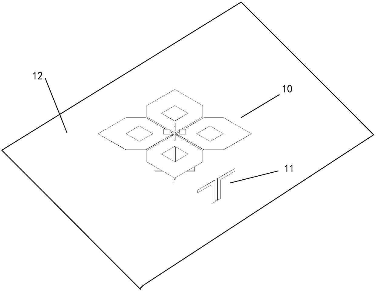
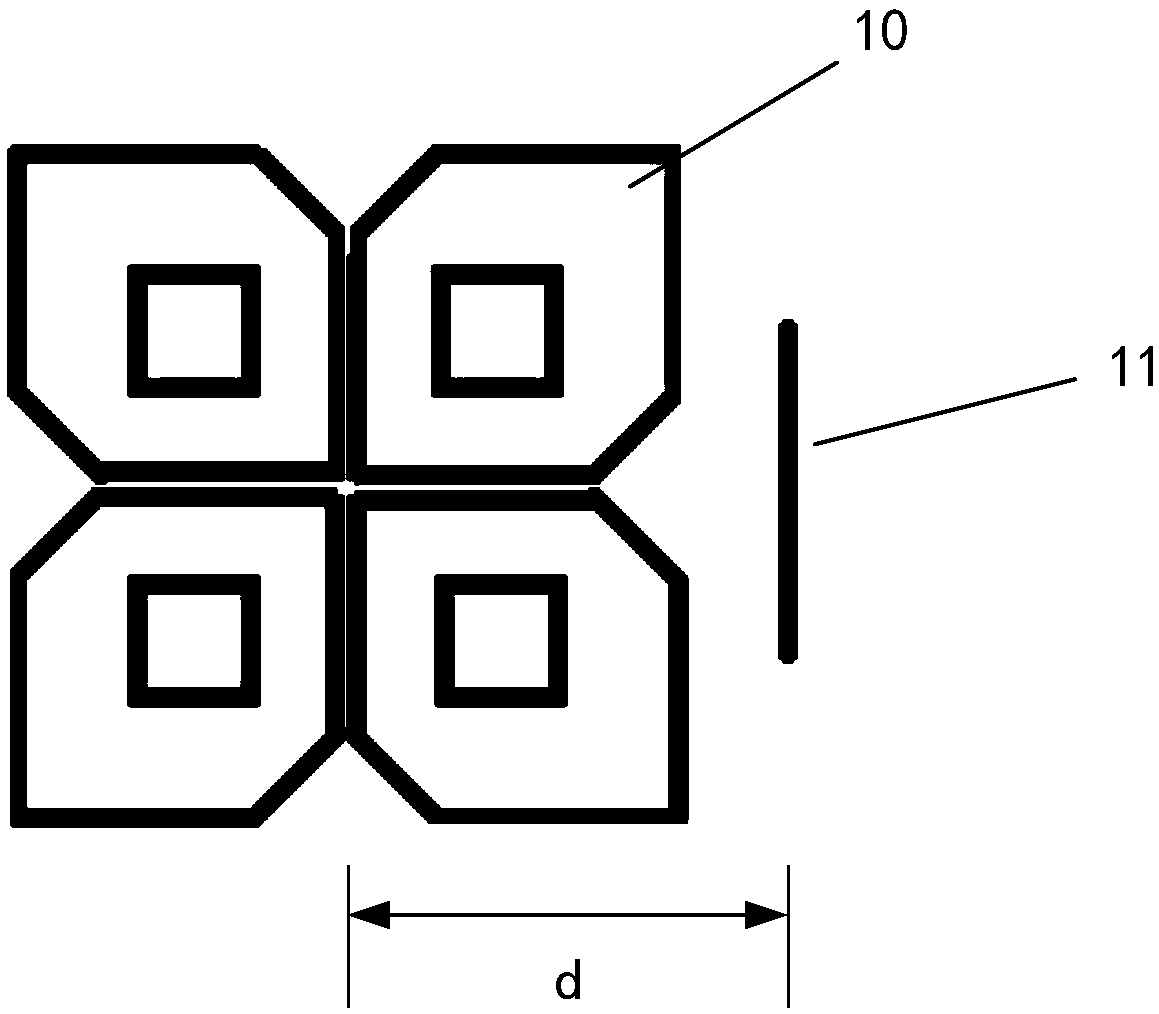
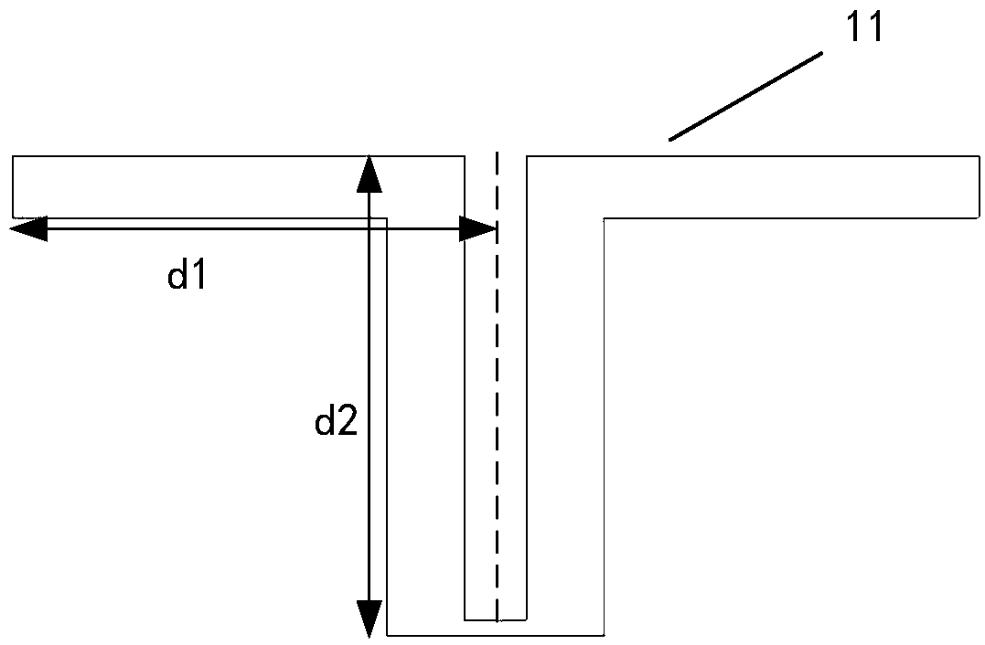
The invention provides an array antenna beam adjustment device and an array antenna with an adjustable beam width, which relate to the technical field of mobile communication base station antennas. The array antenna beam adjustment device comprises at least one parasitic radiation unit; the parasitic radiation unit is arranged beside an array radiation unit with a to-be-adjusted beam width; the parasitic radiation unit is electromagnetically coupled with the array radiation unit in a preset frequency band to change the beam width of the radiation pattern of the array radiation unit in the preset frequency band. According to the array antenna beam adjustment device and the array antenna with the adjustable beam width, the beams of any frequency band of the array antenna can be adjusted, other frequency bands which do not need to be adjusted are not influenced, and ultra wideband of the whole working frequency band is realized.

Description

technical field [0001] The invention relates to the technical field of mobile communication base station antennas, in particular to an array antenna beam adjusting device and an array antenna with adjustable beam width. Background technique [0002] In the cellular mobile communication base station system, in order to improve the system capacity, frequency multiplexing technology is usually used. The sector base station antenna is a convenient implementation method of the frequency reuse technology, which requires the radiation beam of the base station antenna to meet a specific beam width range, such as 65°±6°. Further, with the evolution of mobile communication technology, 2G, 3G, 4G and future 5G require base station antennas to work in ultra-wideband ranges, such as 690-960MHz, 1695-2690MHz, and meet 65°±6°. [0003] Existing methods for changing the lobe width of the radiation beam of the oscillator include changing the form of the oscillator, changing the height of th...

Claims


Application Information

Patent Timeline
Patent Type & Authority Applications(China)
IPC IPC(8): H01Q3/00H01Q3/24H01Q1/36H01Q1/12H01Q19/10H01Q21/00
CPCH01Q1/12H01Q1/36H01Q3/00H01Q3/24H01Q19/104H01Q21/00
Inventor 卜安涛
Owner 南京澳博阳射频技术有限公司
Learn More