Integrated element antenna

A vibrator antenna and metal technology, which is applied in the direction of antenna, antenna grounding device, antenna grounding switch structure connection, etc., can solve the problems that cannot meet the beam requirements of the pattern, and achieve the effect of changing the current distribution and widening the beam width

Pending Publication Date: 2018-10-16
国动科技南京有限公司 +1
View PDF8 Cites 0 Cited by
  • Summary
  • Abstract
  • Description
  • Claims
  • Application Information

AI Technical Summary

Problems solved by technology

Traditional LTE oscillators obviously cannot meet such stringent pattern beam requirements

Method used


Image

  • Integrated element antenna
  • Integrated element antenna
  • Integrated element antenna

Examples


Embodiment Construction

[0021] Below in conjunction with accompanying drawing, the present invention is described in detail:

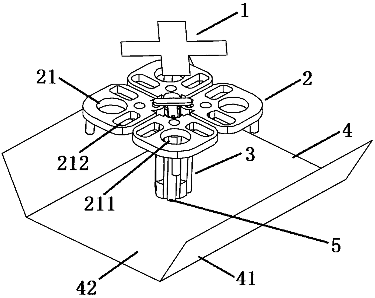
[0022] Such as figure 1 As shown, an integrated dipole antenna includes a director 1, a metal radiating surface 2, a metal balun and a supporting structure 3, a coaxial feeding structure 5 and a reflecting structure. The metal radiating surface 2 is fixed on the upper end of the metal balun and the supporting structure 3 , the reflection structure is fixed on the lower end of the metal balun and the supporting structure 3 , and the director 1 is supported by a bracket and placed directly above the metal radiating surface 2 .

[0023] The coaxial feed structure 5 is composed of an outer conductor and an inner conductor; the coaxial feed structure 5 passes through the reflection structure, and is welded to the center pad of the metal radiation surface along the balun and the support structure 3 .

[0024] The metal radiation surface 2 is composed of four metal sheets, and the ...


PUM


Abstract

The invention discloses an integrated element antenna. The antenna comprises a director, a metal radiating surface, a metal balun and a support structure, a coaxial feeding structure and a reflectingstructure, wherein the metal radiating surface is arranged at an upper end of the metal balun and the support structure, the reflecting structure is arranged at an lower end of the metal balun and thesupport structure, the director is arranged at an upper end of the metal radiating surface, the coaxial feeding structure penetrates the reflecting structure to electrically connected with the metalradiating surface, the metal radiating surface is composed of four metal sheets which are uniformly arranged along a circumference with the metal balun and the support structure as center, a round hole and two square holes are arranged in each metal sheet, and the two square holes are symmetrically distributed at the two sides of a line that connects the center of the round hole and the center ofthe metal balun and the support structure. According to the invention, a current short / open circuit point is created by providing round hole and square hole to change current distribution on surface of antenna elements, thereby widening the beam width of the F-band and A-band directional diagrams.

Description

technical field [0001] The invention relates to the field of wireless communication, in particular to a wireless communication antenna. Background technique [0002] Traditional LTE wireless communication antennas can achieve ±45° dual-polarized directional radiation in the 1.7GHz-2.7GHz frequency band, but their in-band horizontal pattern beamwidth is only 65°±5°. In order to meet the requirements of 2G, 3G, and 4G wireless antennas for integrated design and signal wide-angle coverage, the beamwidth of the horizontal plane pattern of the antenna oscillator needs to be in the F frequency band (1880-1920MHz), A frequency band (2010-2025MHz) and D frequency band (2555MHz) -2635MHz) to 100°, 90°, 65° respectively. At the same time, the roll-off of the horizontal plane pattern beam of the D-band at ±60° must reach more than 9dB. Traditional LTE oscillators are obviously unable to meet such stringent pattern beam requirements. Contents of the invention [0003] The technical...

Claims


Application Information

Patent Timeline
Patent Type & Authority Applications(China)
IPC IPC(8): H01Q1/36H01Q1/48H01Q1/50H01Q19/10H01Q5/28H01Q5/30H01Q5/307
CPCH01Q1/36H01Q1/48H01Q1/50H01Q5/28H01Q5/30H01Q5/307H01Q19/106
Inventor 曹振新傅随道全鑫
Owner 国动科技南京有限公司
Why Eureka
Try Eureka