
Vibrating screen

A technology of vibrating sieve and sieve body, which is applied in the field of vibrating sieve, which can solve the problems of affecting material discharge, poor screening effect, single structure of vibrating sieve, etc., so as to avoid accumulation and improve utilization rate

Inactive Publication Date: 2019-01-04
PINGHU WEIHENG MACHINERY
View PDF0 Cites 4 Cited by
  • Summary
  • Abstract
  • Description
  • Claims
  • Application Information

AI Technical Summary

Problems solved by technology

[0002] The structure of the vibrating screen in the prior art is relatively simple, and it only has a certain vertical screen hole with a fixed aperture size on the sieve plate to sieve materials. In the application of this vibrating screen, the sieve plate can only be roughly Screening of particles smaller than the hole of the sieve plate, the material is only sieved once during the operation, the screening effect is relatively poor, the sieved material falls and easily accumulates together, and even blocks the outlet, affecting the material output material

Method used


Image

  • Vibrating screen
  • Vibrating screen
  • Vibrating screen

Examples


Embodiment

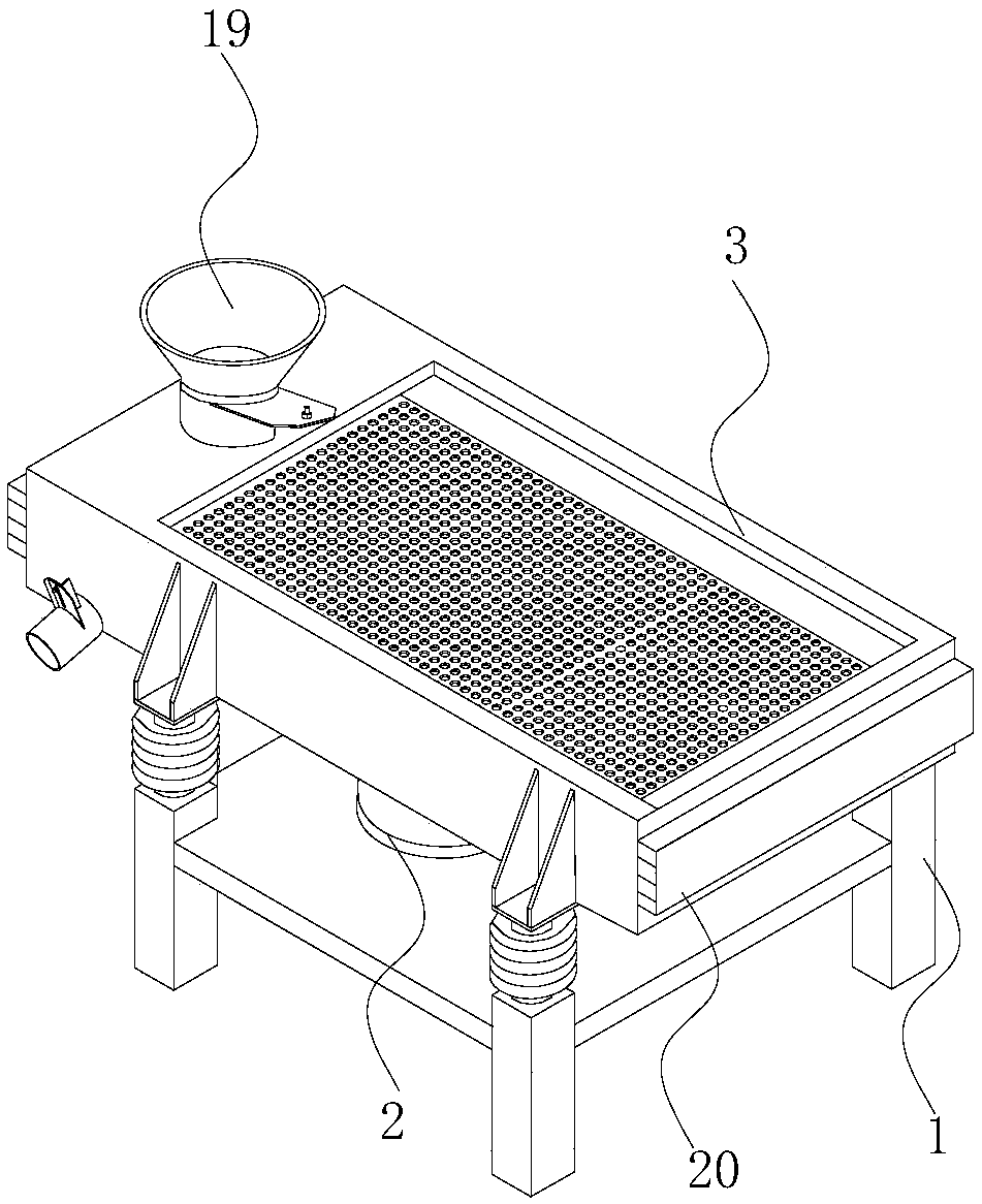
[0027] A vibrating sieve, such as figure 1 , comprising a machine base 1, a screen body 3 arranged on the machine base 1 and a vibrating motor 2 arranged at the bottom of the machine base 1, and a discharge opening 19 is provided at the upper end of the screen body 3.

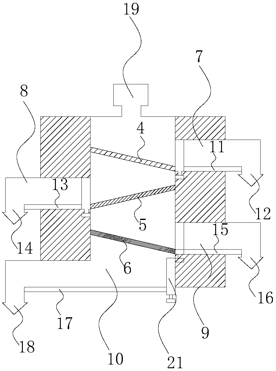
[0028] Such as figure 2 , the sieve body 3 below the feed opening 19 is provided with a first sieve plate 4, a second sieve plate 5 and a third sieve plate 6 in sequence, wherein the first sieve plate 4 and the second sieve plate 5 1. The apertures of the third sieve plate 6 decrease successively to realize multiple screening of materials, and can finely sieve materials to meet the screening needs of materials with different apertures; the first sieve plate 4 and the second sieve plate 5 , The third sieve plate 6 and the sieve body 3 respectively constitute the first sieve channel 7, the second sieve channel 8, the third sieve channel 9 and the fourth sieve channel 10, and the first sieve channel 7, the secon...


PUM


Abstract

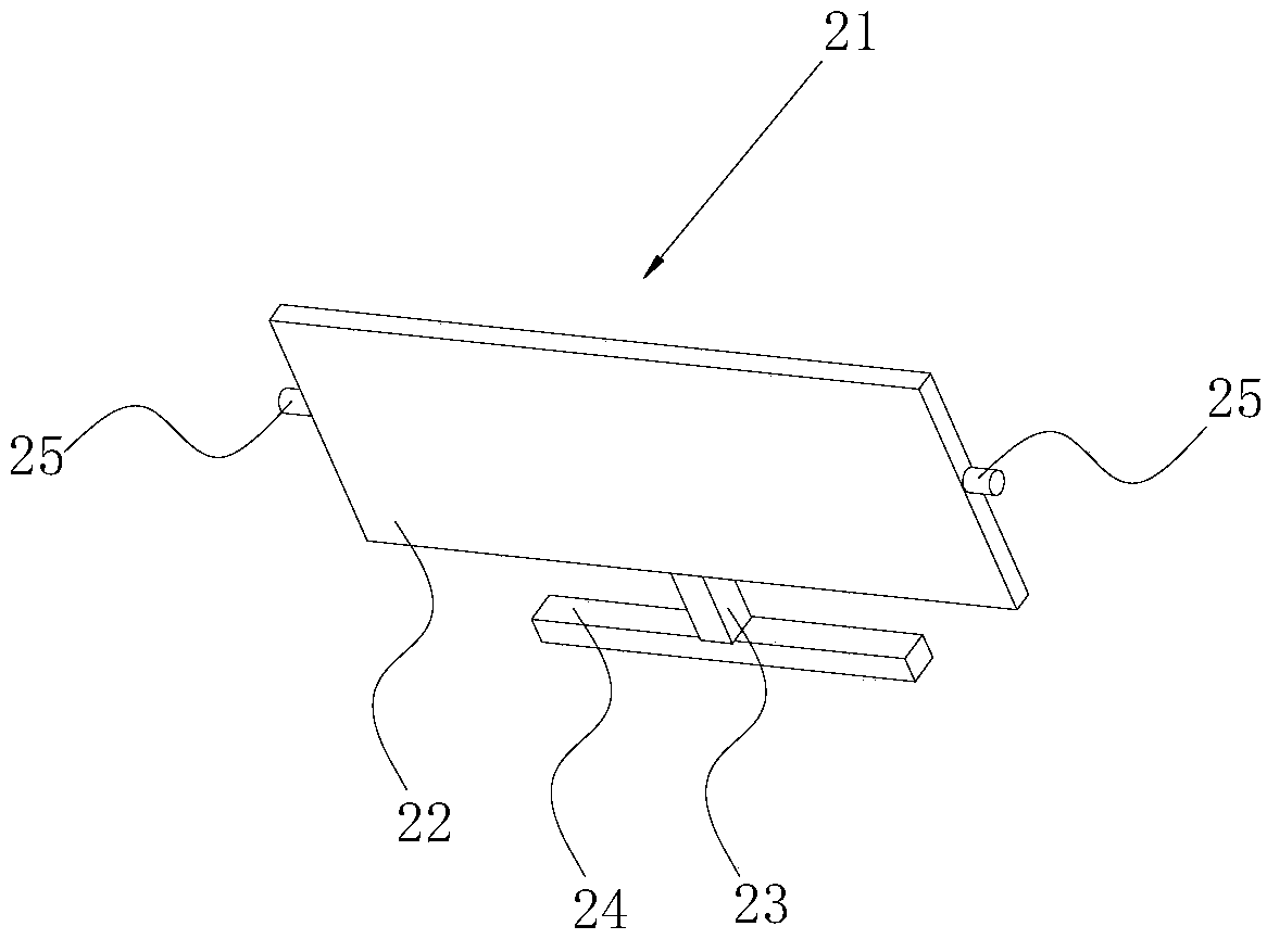
The invention relates to a vibrating screen. The vibrating screen comprises a machine seat, a screen body arranged on the machine seat, and a vibrating motor arranged at the bottom of the machine seat; a falling opening is formed in the upper end of the screen body, and a first screen hole plate, a second screen hole plate and a third screen hole plate are sequentially and obliquely arranged on the position, on the lower portion of the falling opening, of the screen body; the hole diameters of the first screen hole plate, the second screen hole plate and the third screen hole plate are sequentially and gradually decreased; a falling opening is formed in the side edge of the screen body; a pushing device used for pushing fallen materials is arranged at the bottom of the screen body, tracksare arranged at the two sides of the screen body, the pushing device is arranged on the tracks and can move linearly along the tracks; the pushing device comprises a pushing plate vertically arrangedon a bottom plate and a pushing rod fixedly arranged at the bottom of the pushing plate and extending out of the screen body; and an operating rod convenient to operate is fixedly arranged on the pushing rod, idler wheels are arranged on the two sides of the pushing plate correspondingly, and the idler wheels are arranged in the tracks. According to the vibrating screen, the pushing device is arranged at the bottom of the screen body to quickly push the materials, an outlet is not prone to being blocked by the materials, and the materials are discharged rapidly.

Description

technical field [0001] The invention relates to the field of reclaimed rubber processing, in particular to a vibrating sieve for screening granular raw materials during reclaimed rubber manufacturing. Background technique [0002] The structure of the vibrating screen in the prior art is relatively simple, and it only has a certain vertical screen hole with a fixed aperture size on the sieve plate to sieve materials. In the application of this vibrating screen, the sieve plate can only be roughly Screening of particles smaller than the hole of the sieve plate, the material is only sieved once during the operation, the screening effect is relatively poor, the sieved material falls and easily accumulates together, and even blocks the outlet, affecting the material output material. Contents of the invention [0003] The technical problem to be solved by the present invention is to provide a vibrating screen, the outlet of which cannot be blocked by materials, and the materia...

Claims


Application Information

Patent Timeline
IPC IPC(8): B07B1/28B07B1/42B07B1/46
CPCB07B1/28B07B1/42B07B1/46B07B1/4609B07B2201/04
Inventor 徐卫平
Owner PINGHU WEIHENG MACHINERY
Learn More