Self-lubricating hinge

A self-lubricating and hinge technology, which is applied to hinges, hinges with pins, construction, etc., can solve problems such as short lubrication duration, slow hinge speed of lubricating oil, harsh friction sound, etc., and achieve simple and easy disassembly line, improve utilization, and reduce waste

Pending Publication Date: 2019-01-04
NANJING UNIV OF SCI & TECH
View PDF0 Cites 0 Cited by
  • Summary
  • Abstract
  • Description
  • Claims
  • Application Information

AI Technical Summary

Problems solved by technology

[0003] However, the existing ordinary hinges have corresponding disadvantages due to their simple structure, the most important of which is the poor lubrication ability. The ordinary hinges installed on the common wooden doors in the dormitory usually wear off within 3-5 months. Screeching sound when switching
At the same time, ordinary wooden doors are not provided with refueling places, and users can only refuel by dripping oil in the gaps on the hinge surface, and manually opening and closing the door many times to make the lubricating oil soak into most areas of the hinge rods; this method not only causes The lubricating oil is wasted, the door surface cannot be kept clean when refueling, and the lubrication duration is short. On average, the hinge will make a harsh friction sound after 3-5 months, and it needs to be refueled
At present, there are already patents to make oiling holes and oiling grooves for convenient oiling. However, due to the small internal gap of the hinge, oiling in this way will cause the lubricating oil to penetrate into the hinge too slowly, or cause oil spills after excessive oiling. In addition, it still cannot solve the problem of short oil film duration. Therefore, a self-lubricating ordinary hinge device that can quickly refuel is necessary

Method used


Image

  • Self-lubricating hinge
  • Self-lubricating hinge
  • Self-lubricating hinge

Examples


Embodiment Construction

[0017] In order to illustrate the technical scheme and technical purpose of the present invention, the present invention will be further introduced below in conjunction with the accompanying drawings and specific embodiments.

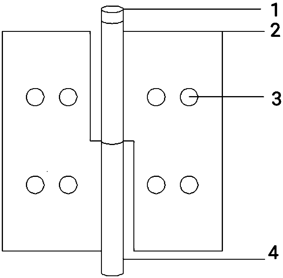
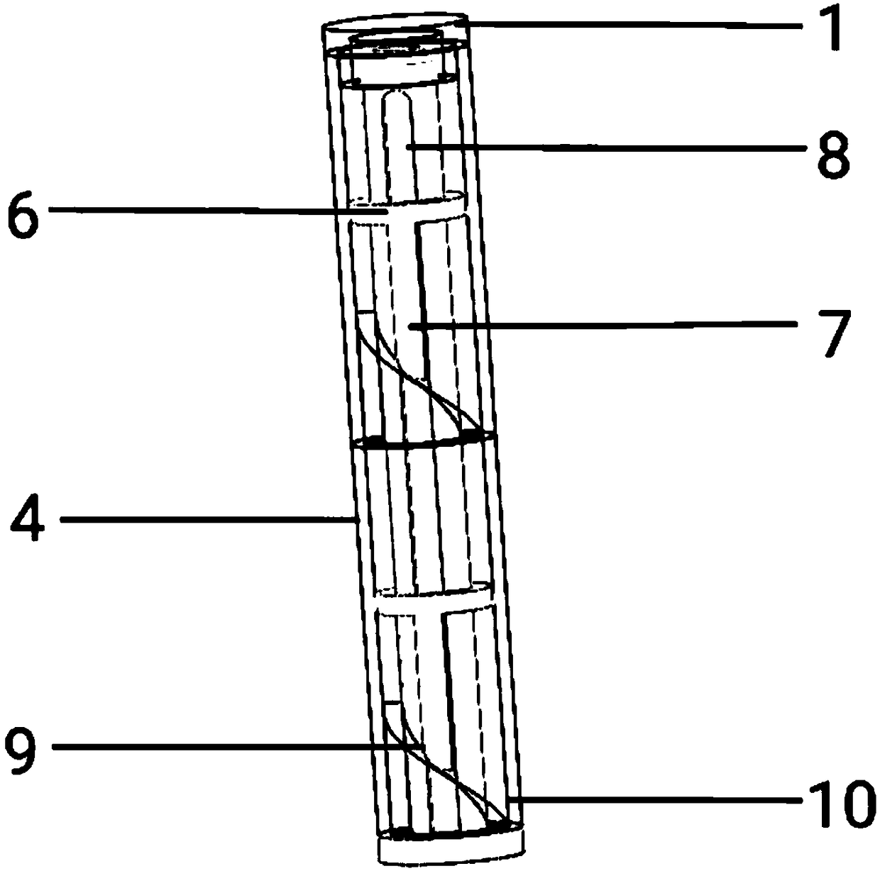
[0018] combine figure 1 , a self-lubricating ordinary hinge of the present invention, comprising two hinge pieces 2, each of the two hinge pieces 2 is fixedly connected to an outer rod 4, and an inner rod 10 is sleeved inside each of the two outer rods 4; The annular gap between the outer rod 4 at the upper end and the inner rod 10 is used as the first oil filling port, and the upper end of the outer rod 4 at the lower end is provided with a second oil filling port 5; the outer rod 4 is provided with a spiral boss 9 inside A push rod 7 is provided between the outer rod 4 and the inner rod 10; the lower end of the push rod 7 is supported on the boss 9, and the upper end is fixedly connected with an oil push ring 6; the oil push ring 6 is set on the inner...


PUM


Abstract

The invention discloses a self-lubricating ordinary hinge comprising two hinge sheets. The two hinge sheets are each fixedly connected with one outer rod, and an inner rod is sleeved with the interiorof each of the two outer rods; an annular gap between each outer rod and the corresponding inner rod which are located at the upper end serves as a first oil filling port, and the upper end of the outer rod located at the lower end is provided with a second oil filling port; a spiral boss is arranged inside each outer rod; a push rod is arranged between each outer rod and the corresponding innerrod; the lower end of each push rod is supported on the corresponding boss, and the upper end is fixedly connected with an oil pushing ring; each oil pushing ring is arranged on the corresponding inner rod in a sleeving manner; each inner rod is provided with a limiting mechanism, so that the corresponding push rod can axially slide along the corresponding inner rod; when the two hinge pieces rotate relative to each other, the outer rods rotate relative to the inner rods; the push rods drive the push rods to slide up and down along the spiral bosses in the outer rods; the oil pushing rings arepushed and driven to slide up and down; and the liquid level of the lubricating oil located on the oil pushing rings moves up and down relative to the inner rods, and the self-lubricating effect is achieved.

Description

technical field [0001] The invention belongs to the field of hardware connectors, in particular to a self-lubricating hinge. Background technique [0002] Hinges are a type of civilian hardware components that are common in daily life. They are often used at the joints of household doors and windows, furniture, and factory and garage doors to play the role of connection and opening and closing. At present, due to the continuous expansion of application fields, hinges of various types and fine craftsmanship have gradually appeared in the market, such as T-shaped hinges, bearing hinges, hydraulic hinges, etc., to meet the needs of different application places. However, the ordinary hinges used in light wooden doors and general wooden furniture are still the best choice for the majority of manufacturers because of their simple structure, low price, and simple manufacturing process. [0003] However, the existing ordinary hinges have corresponding disadvantages due to their sim...

Claims


Application Information

Patent Timeline
Patent Type & Authority Applications(China)
IPC IPC(8): E05D3/02E05D11/02E05D5/10
CPCE05D3/02E05D5/10E05D11/02
Inventor 王修业何璇
Owner NANJING UNIV OF SCI & TECH
Why Eureka
Try Eureka