Two-stage water spraying screw mainframe

A host and screw technology, applied in the field of compressors, can solve the problems of poor overall energy efficiency of the host and can not be completely sealed, and achieve the effects of reliable operation, high pressure range and simple sealing structure

Pending Publication Date: 2019-01-04
NINGBO BAOSI ENERGY EQUIP
View PDF0 Cites 2 Cited by
  • Summary
  • Abstract
  • Description
  • Claims
  • Application Information

AI Technical Summary

Problems solved by technology

However, in the dry two-stage oil-free screw compressors on the market, although the compression cavity is not lubricated by oil, the bearings are still lubricated by oil, which cannot be completely sealed, and the overall energy efficiency of the host is also poor.

Method used


Image

  • Two-stage water spraying screw mainframe
  • Two-stage water spraying screw mainframe

Examples


Embodiment 1

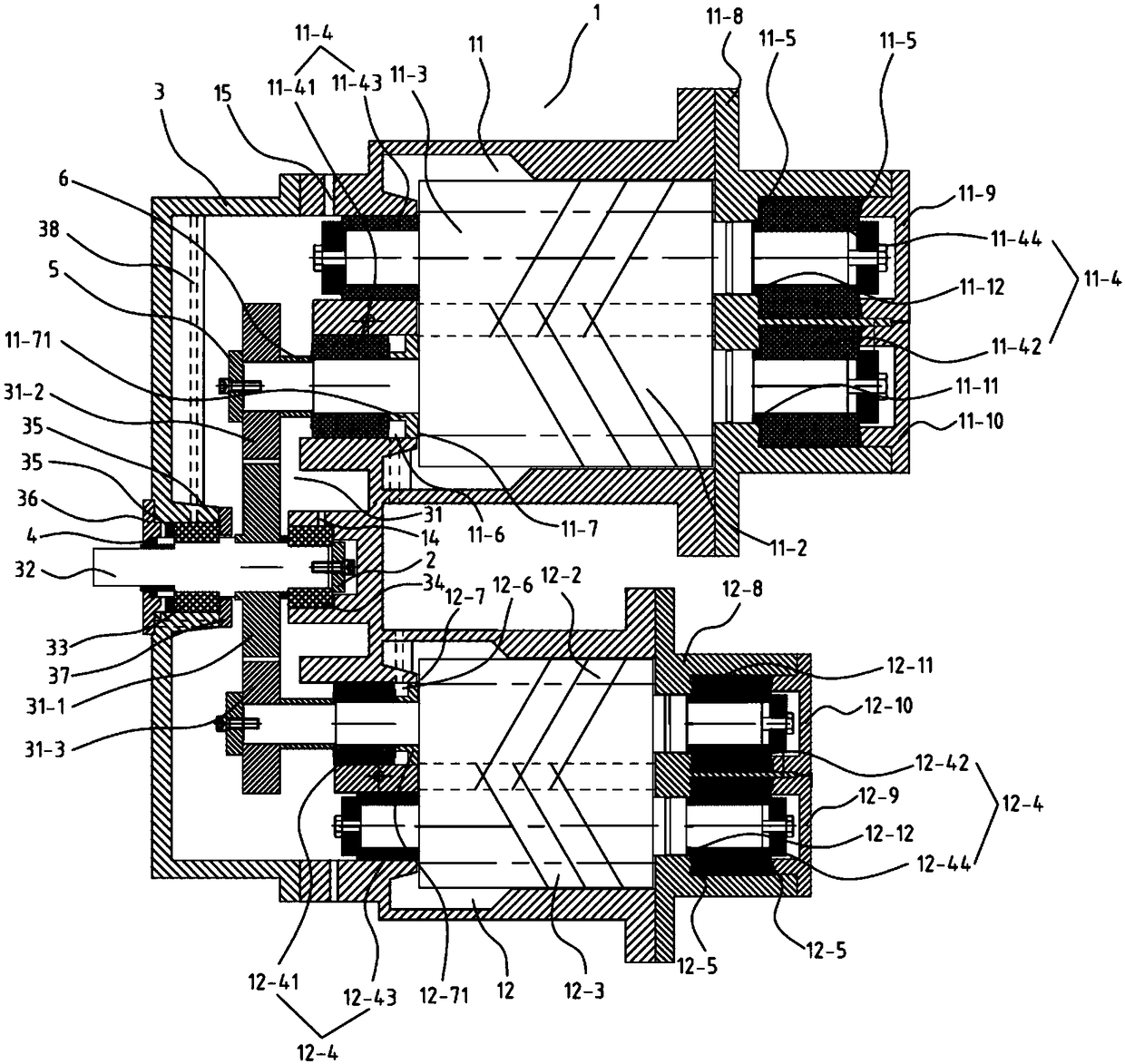
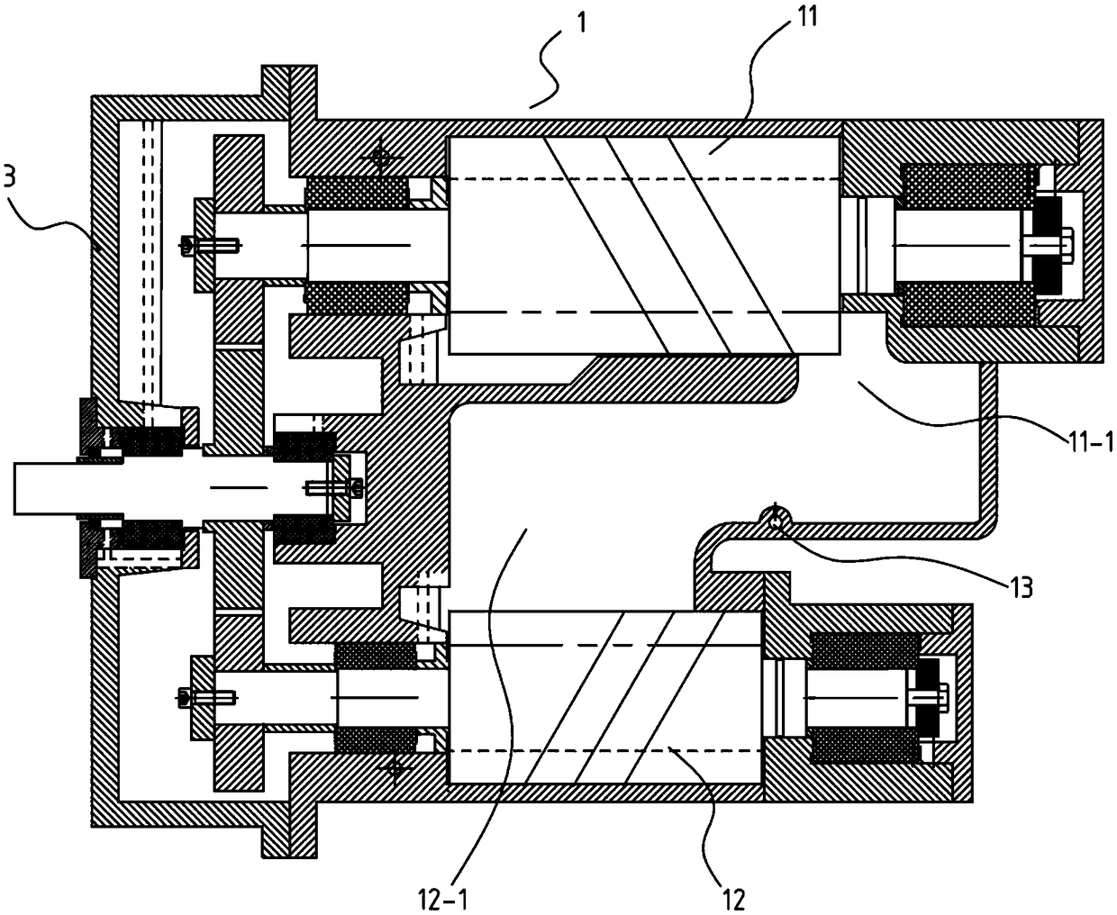
[0025]Embodiment 1: The gear mechanism 31 includes a driving gear 31-1, a primary driven gear 31-2, a secondary driven gear 31-3, a primary driven gear 31-2 and a primary compression chamber 11. The male rotor 11-2 or the first-stage female rotor 11-3 are connected, and a gear washer 6 is sandwiched between the first-stage driven gear 31-2 and the first-stage male rotor 11-2 or the first-stage female rotor 11-3 and passed through The gear pressing block 5 is fastened, and the primary driven gear 31-2 is preferably connected with the primary male rotor 11-2 in the primary compression chamber 11; the secondary driven gear 31-3 is connected with the secondary compression chamber 12 The second-stage male rotor 12-2 or the second-stage female rotor 12-3 are connected, and a gear is interposed between the second-stage driven gear 31-2 and the second-stage male rotor 12-2 or the second-stage female rotor 12-3 The washer 6 is fastened by the gear pressing block 5, and the secondary dr...

Embodiment 2

[0028] Embodiment 2: The two ends of the first-stage male rotor 11-2 in the first-stage compression chamber 11 are respectively installed with a first-stage male front sliding bearing 11-41 and a first-stage male rear sliding bearing 11-42, and are fixed by fasteners; The two ends of the first-stage female rotor 11-3 are respectively equipped with a first-stage female front sliding bearing 11-43 and a first-stage female rear sliding bearing 11-44, and are fixed by fasteners.

[0029] The first-stage positive rear sliding bearing 11-42 and the first-stage female rear sliding bearing 11-44 are respectively provided with first thrust bearings 11-5 along the axial direction, and the first thrust bearing 11-5 on one side is located in a On the first-stage exhaust seat 11-8, the first thrust bearing 11-5 on the other side is located on the first-stage female rear cover 11-9 and the first-stage positive rear cover 11-10; on the first-stage exhaust seat 11-8 The end of the first-stage...

Embodiment 3

[0031] Embodiment 3: The two ends of the two-stage male rotor 12-2 in the two-stage compression chamber 12 are respectively installed with a two-stage male front sliding bearing 12-41 and a second-stage male rear sliding bearing 12-42, and are fixed by fasteners ; The two ends of the secondary female rotor 12-3 are respectively equipped with a secondary female front sliding bearing 12-43 and a secondary female rear sliding bearing 12-44, and are fixed by fasteners.

[0032] Secondary positive rear sliding bearings 12-42 and secondary negative rear sliding bearings 12-44 are respectively provided with second thrust bearings 12-5 along the axial direction, wherein the second thrust bearings 12-5 on one side are located on the second On the first-stage exhaust seat 12-8, the second thrust bearing 12-5 on the other side is located on the second-stage female rear cover 12-9 and the second-stage positive rear cover 12-10; on the second-stage exhaust seat 12-8 The end of the secondar...


PUM


Abstract

The invention relates to a two-stage water spraying screw mainframe, which comprises an air cylinder. The air cylinder is provided with two independent and communicated compression cavities includinga primary compression cavity and a secondary compression cavity. The primary compression cavity is internally provided with an exhaust passage, the secondary compression cavity is internally providedwith an air suction passage, the wall of the air cylinder is provided with a nozzle communicated with an atomizing water cooling mechanism, and the nozzle is positioned between the exhaust passage andthe air suction passage and used for atomizing cooling. A gear box is mounted at air inlet ends of the primary compression cavity and the secondary compression cavity, and a gear mechanism with a spray lubricating effect is arranged in the gear box and connected with a rotor in one of the primary compression cavity and the secondary compression cavity. The two-stage water spraying screw mainframehas advantages that the mainframe integrally adopts a two-stage compression structure and is lubricated through water spraying, and energy saving and environmental friendliness are realized.

Description

technical field [0001] The invention belongs to the technical field of compressors, in particular to a two-stage water-spraying screw main engine. Background technique [0002] As people pay more and more attention to the concept of energy saving, two-stage screw extruders have become the mainstream trend. At present, the common two-stage screw main engine usually adopts oil injection lubrication, and it is impossible to obtain pure air energy when the oil and gas separation technology is not qualified. Due to the increasing demand for pure air power energy in the market, whether the oil-free quality of compressed air and the quality of air supply can be improved in the field of air compressor air supply has become a topic of our concern; especially in food, medical, textile , chemical industry, aerospace and other industries. However, in the dry two-stage oil-free screw compressors on the market, although the compression cavity is not lubricated by oil, the bearings are s...

Claims


Application Information

Patent Timeline
Patent Type & Authority Applications(China)
IPC IPC(8): F04C2/16F04C11/00F04C15/00
CPCF04C2/16F04C11/001F04C15/0042F04C15/0088F04C2240/50
Inventor 张炯焱王立光顾礼照邬剑波
Owner NINGBO BAOSI ENERGY EQUIP
Why Eureka
Try Eureka