Multi-channel oil returning floater gas-liquid separator

A gas-liquid separator and oil float type technology, which is applied in the field of multi-channel oil return float type gas-liquid separators for air source heat pump air conditioning units, can solve the problem of rising oil level, compressor oil shortage, and refrigerant droplets. Into the compressor and other problems, to reduce the risk of liquid hammer, ensure the oil return effect, reduce the effect of harmful overheating

Pending Publication Date: 2019-01-04
HENAN UNIV OF URBAN CONSTR +1
View PDF13 Cites 9 Cited by
  • Summary
  • Abstract
  • Description
  • Claims
  • Application Information

AI Technical Summary

Problems solved by technology

When the external mixed refrigerant enters the tank through the intake liquid pipe, it will flow along the side wall of the tank to form a swirl flow. At this time, the gaseous refrigerant in the mixed refrigerant flows to the top of the tank, and the liquid refrigerant flows in the Under the action of its own gravity, it accumulates to the bottom of the tank, so that the gaseous refrigerant and liquid refrigerant entering the tank can be separated well, but the separation effect is not very ideal, especially when the heat pump air conditioner defrosts, there may be refrigerant liquid The phenomenon of dripping into the compressor
At the same time, the oil return hole of the traditional gas-liquid separator is located at the bottom of the gas-liquid separator. Due to changes in working conditions, a large amount of liquid refrigerant and lubricating oil may remain in the gas-liquid separator, causing the liquid level of the oil layer to rise, and the lubricating oil Unable to return to the compressor through the oil return hole, resulting in the lack of oil in the compressor

Method used


Image

  • Multi-channel oil returning floater gas-liquid separator
  • Multi-channel oil returning floater gas-liquid separator
  • Multi-channel oil returning floater gas-liquid separator

Examples


Embodiment 1

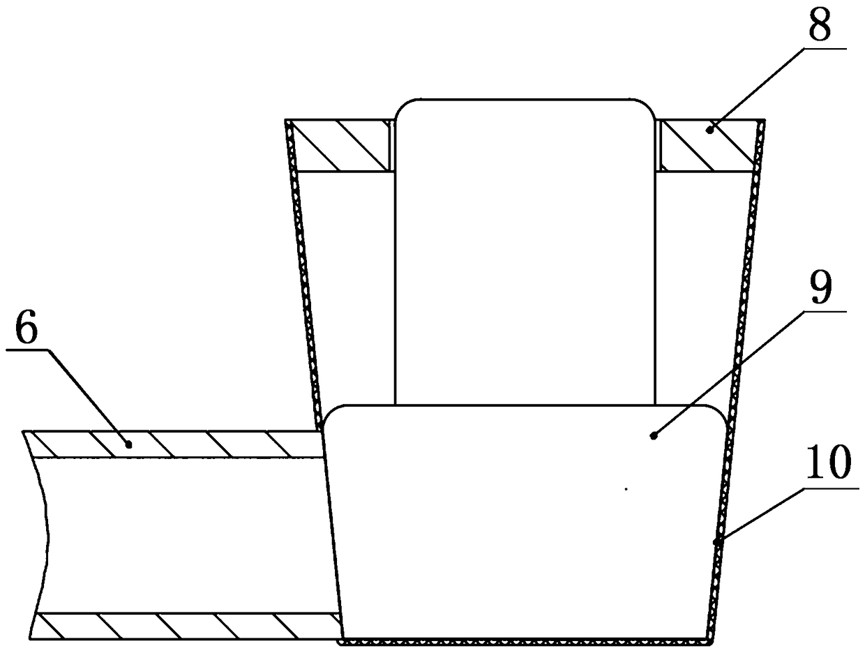
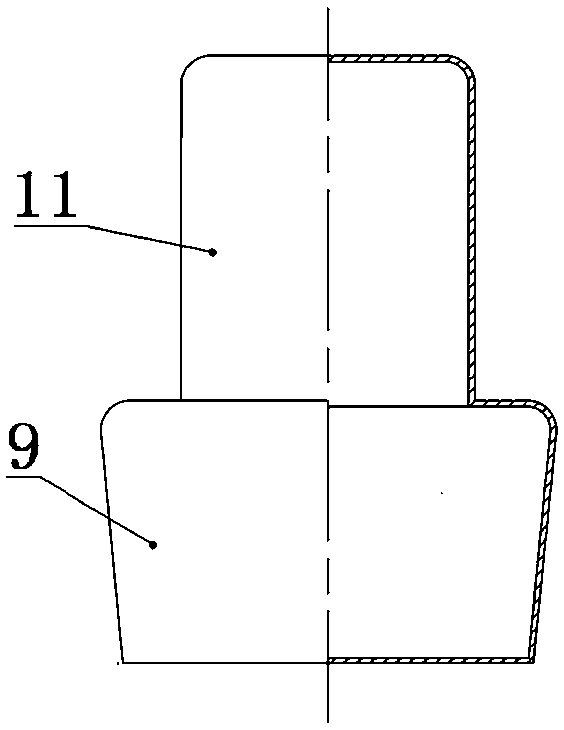
[0035] When the air conditioner unit is running stably, the refrigerant gas in the evaporator enters the gas-liquid separator cylinder 5 connected to the gas-liquid separator inlet 3 through the gas-liquid separator inlet 3 . In the gas-liquid separation cylinder 5, because the gaseous refrigerant needs to enter the interior of the gas-liquid separator through the vent hole on its side wall, the effect of gas-liquid separation is strengthened; at the same time, if the gaseous refrigerant contains impurities, it can also be deposited in the gas-liquid separation cylinder. 5 at the bottom, so that the gas-liquid separation cylinder 5 also has the function of coarse filtration. At this time, the amount of liquid refrigerant in the gas-liquid separator is not large, and the liquid level of the liquid refrigerant should be near the low-level oil return module 4-1. The oil return float 9 floats vertically upward under the action of the guide post 11 and the oil return float screen b...

Embodiment 2

[0037] When the system defrosts or the load changes greatly, the refrigerant gas in the evaporator enters the gas-liquid separation cylinder 5 connected to the gas-liquid separator inlet 3 through the gas-liquid separator inlet 3 . In the gas-liquid separation cylinder 5, the gaseous refrigerant needs to enter into the gas-liquid separator through the air holes on its side wall, which strengthens the effect of gas-liquid separation. At the same time, if the gaseous refrigerant contains impurities, it can also be deposited at the bottom of the gas-liquid separation cylinder 5, so that the gas-liquid separation cylinder 5 also has the function of coarse filtration. At this time, the amount of liquid refrigerant in the gas-liquid separator will increase greatly, and the liquid level of liquid refrigerant will gradually rise, and it will reach the second-lowest oil return module 4-2 and the second-highest oil return module 4 in sequence according to different operating conditions. ...

Embodiment 3

[0039] Under the working condition of system defrosting, while the low-level oil return module 4-2, the next highest oil return module 4-3 and the high-level oil return module 4-4 where the refrigerant liquid level is located return oil, At this time, the oil return module plays the role of cooling the return air, and through the throttling and pressure reduction of the corresponding sub-lower oil return capillary 6-2, second-higher oil return capillary 6-3 and high-level oil return capillary 6-4, the return air The liquid is depressurized and vaporized, absorbing the heat of the superheated gaseous refrigerant to reduce the suction temperature of the compressor and protect the compressor.

[0040] This patent application has the following characteristics: 1. According to the change of the air-conditioning load, multiple oil return pipes with different heights and positions can be used to return oil according to different working conditions, which solves the problem of the exis...


PUM


Abstract

The invention discloses a multi-channel oil returning floater gas-liquid separator. The multi-channel oil returning floater gas-liquid separator comprises a separator body shell, and an end cover arranged at the top of the body shell; and a gas-liquid separation system connected with an evaporator of an air conditioning unit and a multi-channel oil returning system connected with an intake port ofa compressor are arranged in the separator body shell. The multi-channel oil returning floater gas-liquid separator has the following characteristics: (1) multiple oil returning pipes with differentheight positions are used for returning oil according to the load change of an air conditioner and different working conditions, so that the defect of incapability of adjusting the oil returning according to the oil level change in the load change of the air conditioner due to fixed position of an oil returning hole of a traditional gas-liquid separator is solved, and the oil returning effect is effectively guaranteed; (2) a gas-liquid separation cylinder is arranged in an inlet of the gas-liquid separator for improving the gas-liquid separation effect; and (3) the oil returning pipes achievea throttling effect, so that liquid-state refrigerants in the returned oil are gasified, and the liquid shock risk of the compressor is reduced; and meanwhile, returned gas can be cooled to reduce harmful overheat and energy consumption.

Description

technical field [0001] The invention relates to a gas-liquid separator for an air-conditioning unit, in particular to a multi-channel oil return float type gas-liquid separator for an air-source heat pump air-conditioning unit. technical background [0002] With the improvement of people's material living standards, the requirements for the comfort of the living environment are getting higher and higher, and air conditioners have become an indispensable living facility in life. At the same time, the problem of unreasonable energy utilization in our country is very prominent. A large amount of coal for heating in winter is one of the main reasons for serious air pollution in winter. According to the policy instruction of "Winter Clean Heating Plan in Northern Region (2017-2021)" jointly issued by ten ministries and commissions of the country, the "coal to clean energy" project in all parts of the north will be completed by the end of 2021. [0003] Driven by government polic...

Claims


Application Information

Patent Timeline
Patent Type & Authority Applications(China)
IPC IPC(8): F25B43/00F25B31/00
CPCF25B31/004F25B43/006F25B2500/28
Inventor 周前张志远王伟山周志一饶培军杨海林赵晓东
Owner HENAN UNIV OF URBAN CONSTR
Why Eureka
Try Eureka