Sliding valve type inverse proportion pressure reduction valve

A pressure reducing valve, inverse proportional technology, applied in the field of hydraulic control, can solve problems such as difficulty in integrated processing, and achieve the effects of reducing manufacturing costs, high control accuracy, and reducing repetitive labor.

Active Publication Date: 2018-05-04
BEIJING INSTITUTE OF TECHNOLOGYGY
View PDF7 Cites 0 Cited by
  • Summary
  • Abstract
  • Description
  • Claims
  • Application Information

AI Technical Summary

Problems solved by technology

[0004] The purpose of the present invention is to provide a slide valve type inverse proportional pressure reducing valve in order to solve the problem of difficulty in one-piece processing in the prior art

Method used


Image

  • Sliding valve type inverse proportion pressure reduction valve
  • Sliding valve type inverse proportion pressure reduction valve
  • Sliding valve type inverse proportion pressure reduction valve

Examples


Embodiment 1

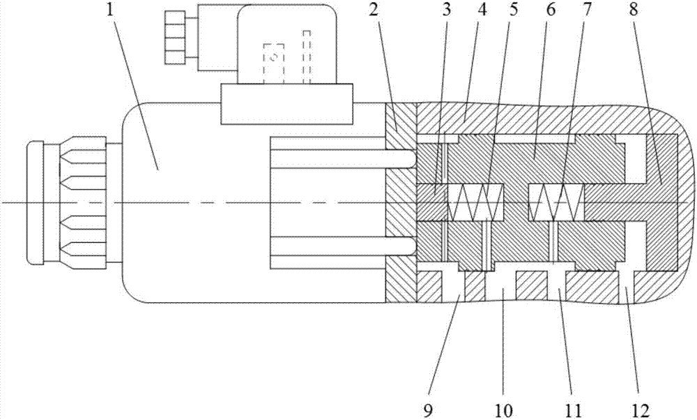
[0030] A slide valve type inverse proportional pressure reducing valve, such as figure 1 As shown, it includes: proportional electromagnet 1, baffle 2, cylindrical plug 3, valve body 4, first return spring 5, valve core 6, second return spring 7, piston 8;

[0031] The valve body 4 is a bottom-sealed hollow equal-diameter cylindrical cavity; the side wall is provided with an oil port 9, a working oil port 10, an oil inlet 11, and an oil drain 12;

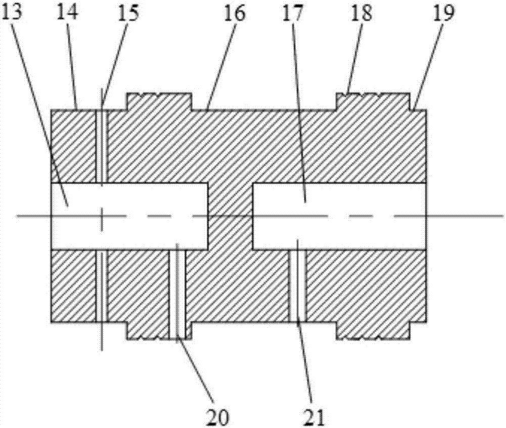
[0032] Such as figure 2 As shown, the valve core 6 has a cylindrical structure, and blind holes are respectively opened inward along the two ends of the cylinder; on the side walls of the cylinder corresponding to the two blind holes, two circumferentially symmetrical first pressure guiding holes 20 and second Pressure guiding hole 21; Throttle holes 15 are respectively opened on the cylindrical side wall corresponding to the blind hole close to the baffle 2; The throttle hole 15, the first pressure hole 20, and the second pressure hole ...


PUM


Abstract

The invention relates to a sliding valve type inverse proportion pressure reduction valve, and belongs to the field of hydraulic control. The valve comprises a proportion electromagnet, a baffle, a cylindrical plug, a valve body, a first reset spring, a valve element, a second reset spring and a piston; valve cavity equal-diameter machining is adopted, when the electromagnet does not work, work pressure output by the pressure reduction valve is maximum, along with current increase, electromagnetic thrust output by the electromagnet is increased, work pressure of the pressure reduction valve isgradually reduced, hydraulic pressure in a valve element work cavity, spring force and electromagnetic force are balanced, and hydraulic oil path pressure adjusting is achieved. The proportion pressure reduction valve is high in control precision, system work stability can be improved, the structure is simple and easy to machine, the manufacturing cost is low, and assembling complexity is reduced.

Description

Technical field [0001] The invention relates to a slide valve type inverse proportional pressure reducing valve, in particular to a slide valve type inverse proportional pressure reducing valve which can continuously and steplessly control the oil pressure in an automobile automatic transmission hydraulic system or an industrial hydraulic automatic control system, belonging to Hydraulic control field. Background technique [0002] The proportional pressure reducing valve is a control valve that uses a solenoid energization change to control a proportional electromagnet to adjust the valve core opening of the pressure reducing valve. When the solenoid coil is energized, the solenoid force opens the valve core, and the hydraulic oil flows through the valve cavity and acts on the surface of the valve core to generate pressure, which forms a force balance with the spring force and the electromagnetic force, thereby controlling the pressure of the hydraulic oil circuit. Since the ele...

Claims


Application Information

Patent Timeline
Patent Type & Authority Applications(China)
IPC IPC(8): F16K11/07F16K31/06
CPCF16K11/0708F16K31/0613
Inventor 吴维肖冰清苑士华胡纪滨刘辉
Owner BEIJING INSTITUTE OF TECHNOLOGYGY
Why Eureka
Try Eureka