A high-speed camera imaging distortion calibration device and a method

A high-speed camera and calibration device technology, applied in the field of photography, can solve problems such as large measurement errors and inaccurate test parameters

Active Publication Date: 2019-01-04
南京恒泰利信电子科技有限公司
View PDF11 Cites 19 Cited by
  • Summary
  • Abstract
  • Description
  • Claims
  • Application Information

AI Technical Summary

Problems solved by technology

[0003] In view of the above analysis, the present invention aims to provide a high-speed camera imaging distortion calibration device and method to solve the problem that the existing high-speed camera has a large measurement error, resulting in inaccurate measured test parameters

Method used


Image

  • A high-speed camera imaging distortion calibration device and a method
  • A high-speed camera imaging distortion calibration device and a method
  • A high-speed camera imaging distortion calibration device and a method

Examples


Embodiment Construction

[0049] Preferred embodiments of the present invention will be specifically described below in conjunction with the accompanying drawings, wherein the accompanying drawings constitute a part of the application and are used together with the embodiments of the present invention to explain the principle of the present invention.

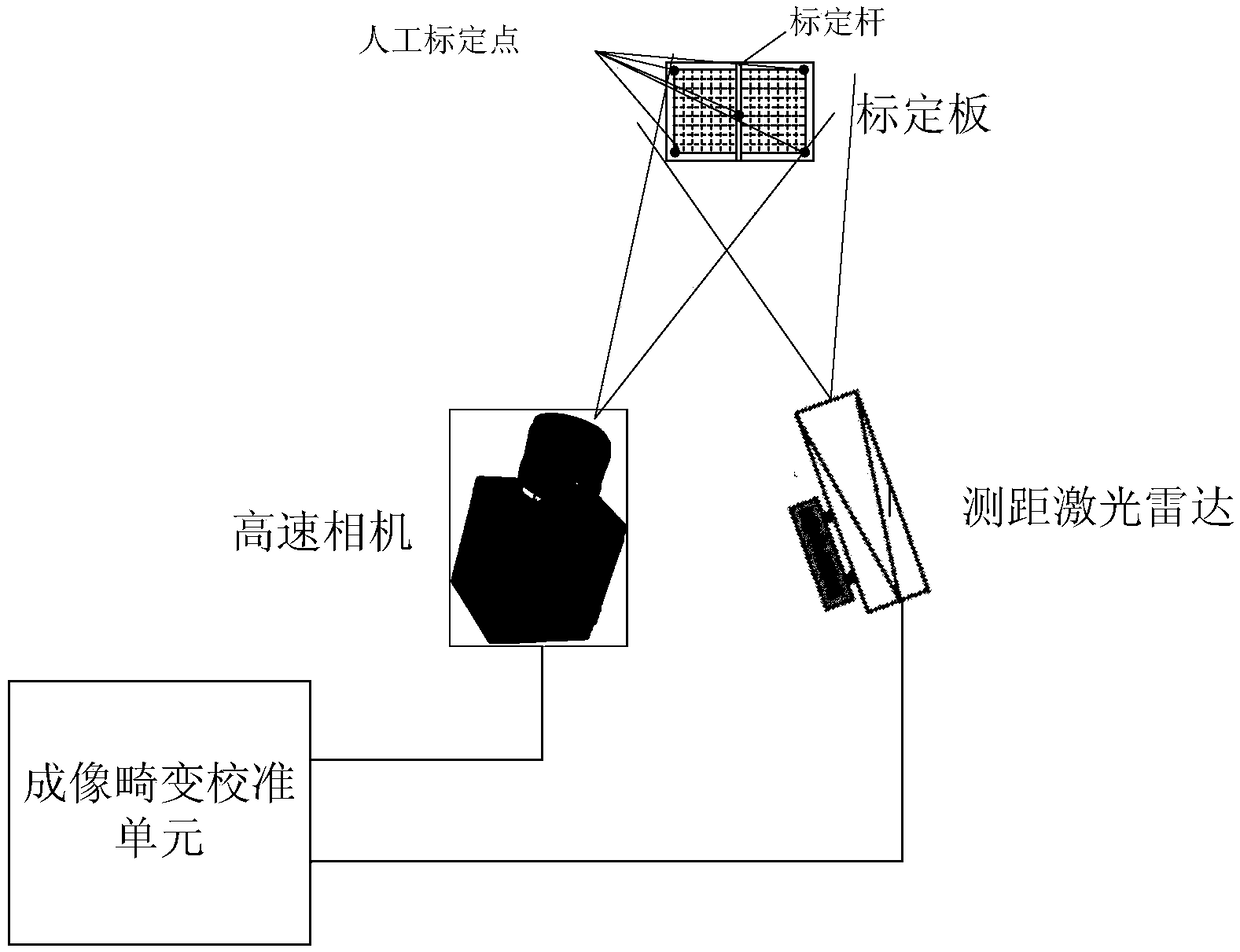
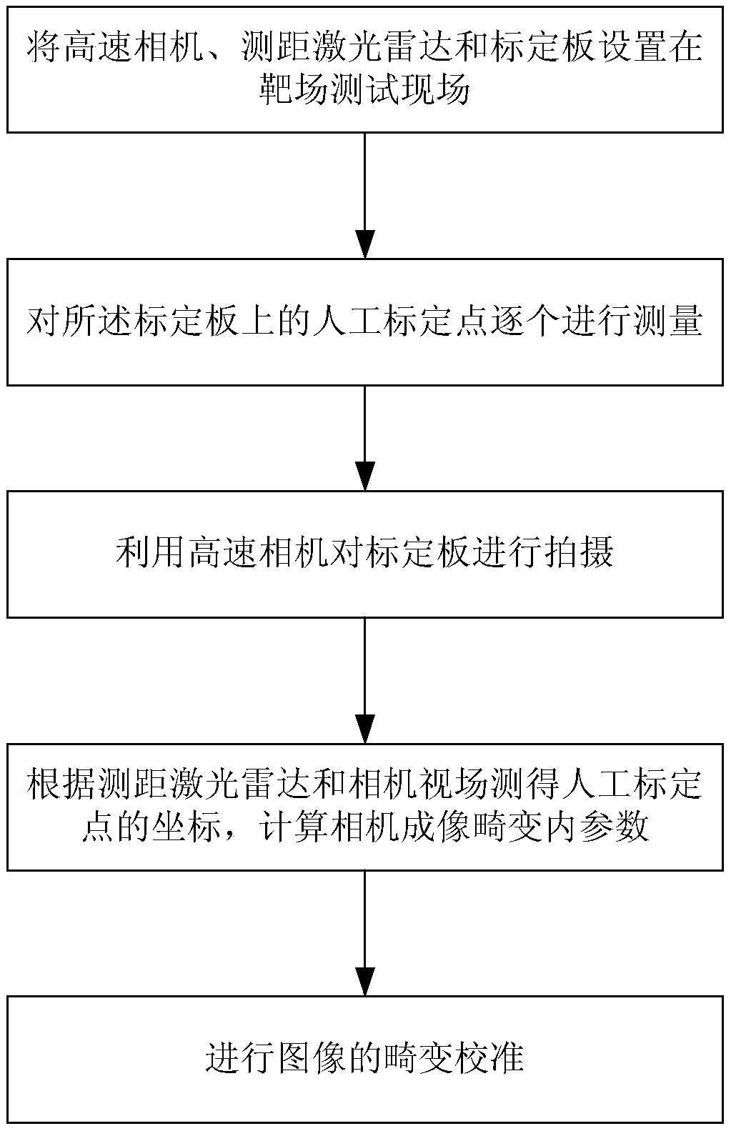
[0050] An embodiment of the present invention provides a high-speed camera imaging distortion calibration device, such as figure 1 As shown, it includes calibration board, ranging lidar, high-speed camera and imaging distortion calibration unit.

[0051] The calibration board is in the field of view of the high-speed camera and the ranging laser radar, and is in the shape of a grid, with at least 5 manual calibration points, including the center D1 of the calibration board and the four corner points of the calibration board. It is possible to reduce the calibration uncertainty and error by increasing the number of calibration points, for example, by add...


PUM


Abstract

The invention relates to a high-speed camera imaging distortion calibration device and method, which comprises a calibration plate, a ranging laser radar, a high-speed camera and an imaging distortioncalibration unit. When imaging distortion is calibrated, the calibration plate is located in the field of view of the high-speed camera and the ranging lidar; the ranging lidar measures the positioncoordinates of the manual calibration points on the calibration board, and the high-speed camera captures a calibration board image including the manual calibration points; the imaging distortion calibration unit takes the coordinates of the manual calibration points measured by the ranging lidar as a reference, calibrates the coordinates of the manual calibration points on the calibration board image taken by the high-speed camera, and calculates the camera internal parameters related to the camera imaging distortion; the imaging distortion calibration unit performs real-time distortion calibration on images captured by the high-speed camera according to the internal parameters.

Description

technical field [0001] The invention relates to the technical field of photography, in particular to a high-speed camera imaging distortion calibration device and method. Background technique [0002] High-speed photography is an important test method in the research of detonation physics, shock wave physics, accelerator physics and plasma experiments. High-speed cameras use optical imaging to track the test process in real time and obtain corresponding parameters. The high-speed camera can not only record the high-speed movement process, but also perform visual measurement. It is currently the only blasting parameter measurement device that can simultaneously acquire target images and high-precision trajectories. At present, the high-speed cameras widely used in the research of blasting process tests generally face the problems of inaccurate exposure time and frame loss. In terms of time, the exposure time error and frame loss will cause misjudgment of the speed, accelerat...

Claims


Application Information

Patent Timeline
Patent Type & Authority Applications(China)
IPC IPC(8): G06T7/80
CPCG06T2207/30204G06T7/80
Inventor 张小富刘天植付晨
Owner 南京恒泰利信电子科技有限公司
Why Eureka
Try Eureka