A high-speed camera calibration system and method

A high-speed camera and calibration system technology, applied in the field of photography, can solve problems such as affecting blasting power, inaccurate time estimation, affecting the development progress of weapon systems, etc.

Active Publication Date: 2020-02-18
南京恒泰利信电子科技有限公司
View PDF5 Cites 0 Cited by
  • Summary
  • Abstract
  • Description
  • Claims
  • Application Information

AI Technical Summary

Problems solved by technology

At present, the high-speed cameras widely used in the research of blasting process tests generally face the problems of inaccurate exposure time and frame loss.
In terms of time, the exposure time error and frame loss will cause misjudgment of the speed, acceleration and trajectory of the debris during the blasting process, and the estimation of the time between the first blasting and the second blasting will be inaccurate; in terms of space, high-speed cameras If there is distortion in the captured image, it will lead to misjudgment of the trajectory of the debris, which will greatly affect the research on blasting power, which has brought trouble to weapon performance evaluation and design optimization, and has affected the development progress of this type of weapon system.
After analysis, the main reason for this error is that the shooting range lacks technical means for accurate measurement and calibration of high-speed camera exposure time inaccuracy, frame loss and target imaging distortion, which makes this type of equipment unable to obtain effective measurement guarantee for a long time

Method used


Image

  • A high-speed camera calibration system and method
  • A high-speed camera calibration system and method
  • A high-speed camera calibration system and method

Examples


Embodiment Construction

[0065] Preferred embodiments of the present invention will be specifically described below in conjunction with the accompanying drawings, wherein the accompanying drawings constitute a part of the application and are used together with the embodiments of the present invention to explain the principles of the present invention.

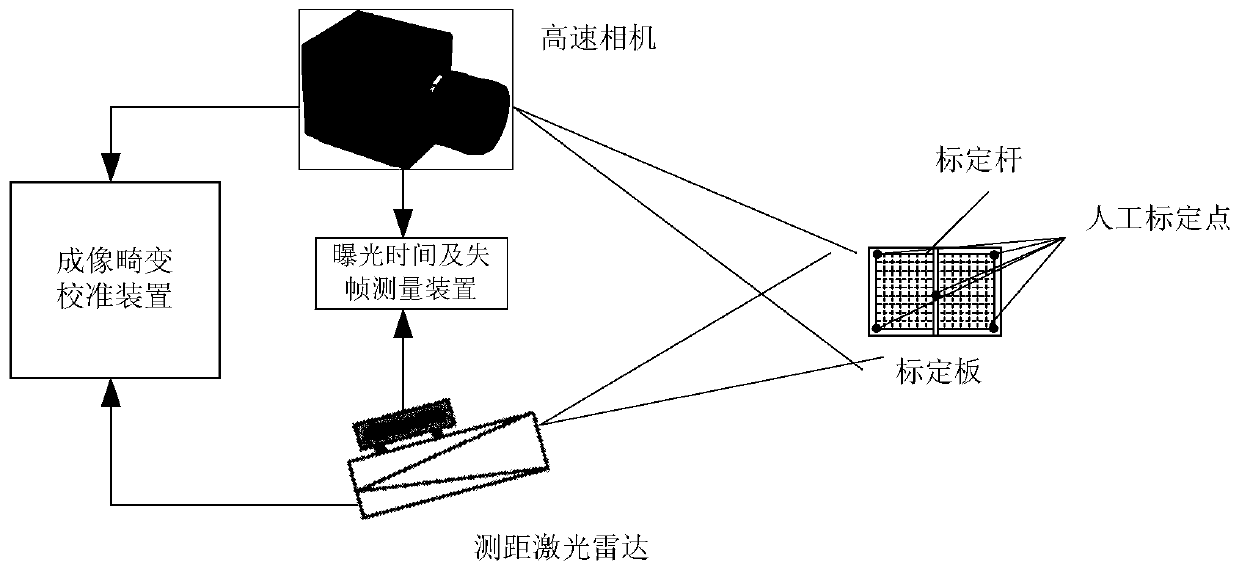
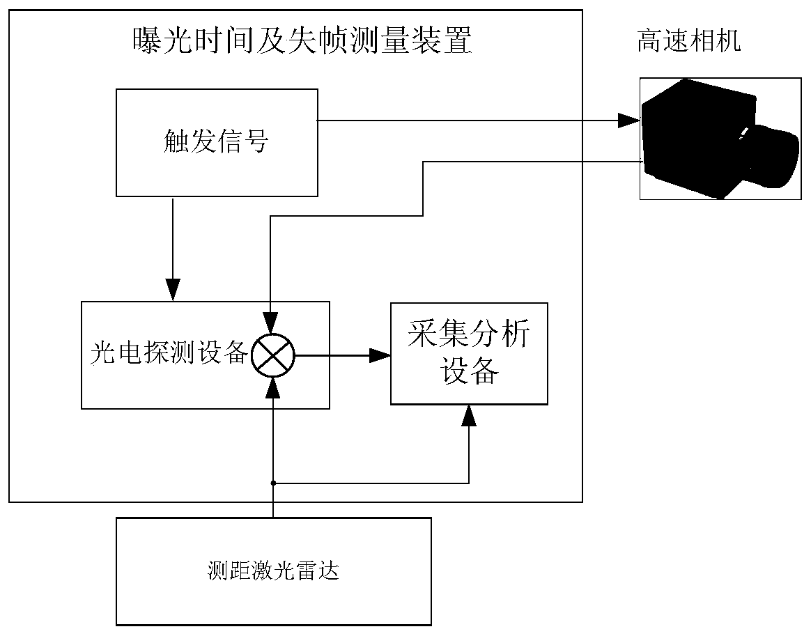
[0066] An embodiment of the present invention provides a high-speed camera calibration system, such as figure 1 As shown, including calibration board, ranging laser radar, high-speed camera, exposure time and frame loss measurement device and imaging distortion calibration device;

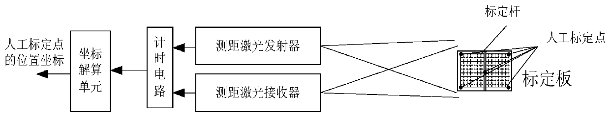
[0067] The calibration plate is a quadrilateral grid-shaped flat plate; a plurality of artificial calibration points are arranged on the grid-shaped flat plate;

[0068] The ranging laser radar generates a high repetition frequency laser signal, measures the position coordinates of the manual calibration point, transmits the coordinate information to the imaging distortion ...


PUM


Abstract

The invention relates to a high-speed camera calibration system and method. The high-speed camera calibration system includes a calibration plate, a distance measuring laser radar, a high-speed camera, an exposure time and frame loss measurement device, and an imaging distortion calibration device. The system and method combine high-precision picosecond laser ranging technology with camera parameter calibration algorithm to determine the camera focal length and distortion coefficient, optimize the distortion matrix, form an accurate three-dimensional restoration algorithm from camera image to spatial position, and realize camera imaging distortion Space calibration; the measurement reference clock frequency is 4-5 orders of magnitude higher than the measured high-speed camera frequency; the acquisition and analysis equipment with a sampling rate of 25GHz is used to collect the exposure time of the high-speed camera, and the measurement obtains high-precision exposure time and frame loss rate. Provide a data basis for calibrating the experimental parameters obtained by the high-speed camera.

Description

technical field [0001] The invention relates to the technical field of photography, in particular to a high-speed camera calibration system and method. Background technique [0002] High-speed photography is an important test method in the research of detonation physics, shock wave physics, accelerator physics and plasma experiments. High-speed cameras use optical imaging to track the test process in real time and obtain corresponding parameters. The high-speed camera can not only record the high-speed movement process, but also perform visual measurement. It is currently the only blasting parameter measurement device that can simultaneously acquire target images and high-precision trajectories. At present, the high-speed cameras widely used in the research of blasting process tests generally face the problems of inaccurate exposure time and frame loss. In terms of time, the exposure time error and frame loss will cause misjudgment of the speed, acceleration and trajectory ...

Claims


Application Information

Patent Timeline
Patent Type & Authority Patents(China)
IPC IPC(8): H04B10/50H04B10/508H04N5/235H04N17/00
CPCH04B10/503H04B10/508H04N17/002H04N23/73
Inventor 张小富刘天植付晨
Owner 南京恒泰利信电子科技有限公司
Why Eureka
Try Eureka