A variable inductor with continuously adjustable inductance

An inductor and variable technology, which is applied in the direction of continuously variable inductors/transformers, variable inductors, inductors, etc., can solve the problems that the inductance cannot be continuously adjusted and intermittently adjusted, and achieve It is convenient for manual winding, maintains continuity, and has the effect of high precision of inductance

Pending Publication Date: 2019-01-04
FUJIAN DINGYANG INFORMATION TECH CO LTD
View PDF0 Cites 0 Cited by
  • Summary
  • Abstract
  • Description
  • Claims
  • Application Information

AI Technical Summary

Problems solved by technology

[0002] The existing loading coil can realize variable adjustment of inductance, but it can only be adjusted intermittently, and cannot realize continuous adjustment of inductance
Although the existing spherical variable inductors can realize the continuous adjustment of the inductance within a certain range, they can only realize the continuous adjustment of the inductance within a certain range

Method used


Image

  • A variable inductor with continuously adjustable inductance
  • A variable inductor with continuously adjustable inductance
  • A variable inductor with continuously adjustable inductance

Examples


Embodiment 1

[0044] Please refer to Figure 1 to Figure 14 , Embodiment 1 provided by the present invention is:

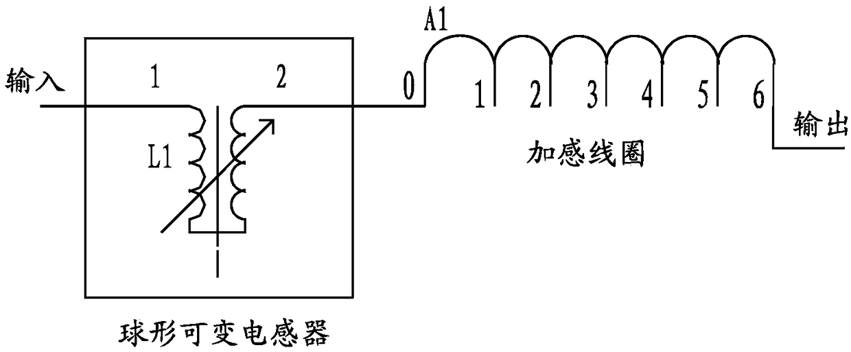
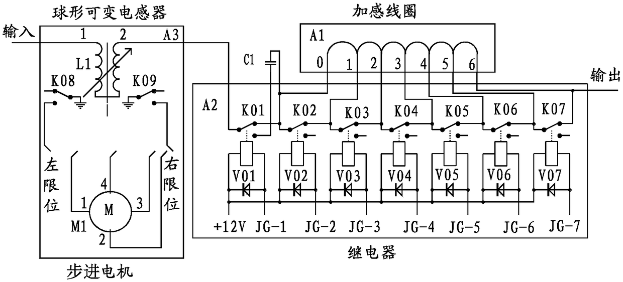
[0045] A variable inductor with continuously adjustable inductance, comprising a first variable inductor 1 and a second variable inductor 2, the first variable inductor 1 includes a loading coil 12, the The loading coil 12 includes at least one tap 121; the second variable inductor 2 includes a spherical variable inductor 21, and the spherical variable inductor 21 includes a rotor core 211, a rotor coil, a stator core 212, stator coil, rotor bracket 213 and stator bracket 214, the rotor core 211 is spherical, the spherical surface of the rotor core 211 is distributed with helical first grooves 2111, and the rotor coil is wound on the first In a groove 2111, the stator core 212 is hollow spherical, and the spherical surface of the stator core 212 is distributed with helical second grooves 2121, and the stator coil is wound in the second groove 2121, The rotor core 211 is insta...

Embodiment 2

[0050] Embodiment two provided by the present invention is:

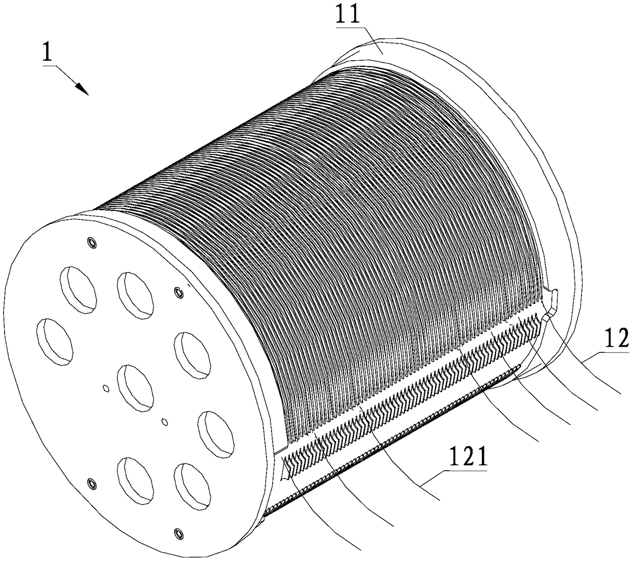
[0051] On the basis of the first embodiment, further, the first variable inductor 1 further includes a bobbin 11, the loading coil 12 is wound on the bobbin 11, and the bobbin 11 is provided with There are a plurality of clamping projections 111 arranged side by side in the circumferential direction, the distance between adjacent clamping projections 111 is adapted to the diameter of the loading coil 12, and the height of the clamping projections 111 is and the width are smaller than the diameter of the loading coil 12, and each of the clamping protrusions 111 is provided with a routing opening 1111, and the loading coils 12 are alternately stacked and wound on the bobbin 11. The loading coil 12 on the bottom layer is wound on both sides of the clamping protrusion 111, and the loading coil 12 on the top layer is wound close to and wound between two adjacent turns of the loading coil 12 on the bottom layer. During w...

Embodiment 3

[0055] Embodiment three provided by the present invention is:

[0056] On the basis of the second embodiment, further, each of the clamping protrusions 111 is provided with a retaining protrusion 1112, and the height of the retaining protrusion 1112 is greater than or equal to the diameter of the loading coil 12 2 times, the wire retaining protrusion 1112 is in contact with the wire routing opening 1111, and the wire retaining protrusion 1112 is located at the front end of the wire routing opening 1111 along the wire winding direction.

[0057] The wire retaining protrusion 1112 can not only position the loading coil 12 on the bottom layer, but also position the loading coil 12 on the top layer, thereby further improving the winding precision of the loading coil 12 in length and facilitating manual winding. During the process of manufacturing the loading coil 12, the loading coil 12 located on the top layer can be accurately positioned, which is convenient for manual mass prod...


PUM


Abstract

The invention provides a variable inductor with continuously adjustable inductance, comprising a first variable inductor and a second variable inductor, wherein the first variable inductor comprises an inductance coil; The second variable inductor comprises a spherical variable inductor, the spherical variable inductor comprises a rotor core, a rotor coil, a stator core, a stator coil, a rotor bracket and a stator bracket, wherein the rotor core is spherical, the rotor coil is wound on the spherical surface of the rotor core, the stator core is hollow spherical, the stator coil is wound on thespherical surface of the stator core, and the rotor core is installed in the stator core; The first variable inductor is connected in series with the second variable inductor, and the inductance amount of the second variable inductor is greater than a maximum value of an inductance amount difference in sections of the first variable inductor separated by the tap, and greater than a minimum inductance amount in sections of the first variable inductor. The inductance is continuously adjustable in a variety of ranges.

Description

technical field [0001] The invention relates to the technical field of variable inductors, in particular to a variable inductor with continuously adjustable inductance. Background technique [0002] The existing loading coil can realize the variable adjustment of the inductance, but it can only be adjusted intermittently, and cannot realize the continuous adjustment of the inductance. Although the existing spherical variable inductors can realize the continuous adjustment of the inductance within a certain range, they can only realize the continuous adjustment of the inductance within a certain range. Contents of the invention [0003] The technical problem to be solved by the present invention is to provide a variable inductor with continuously adjustable inductance to realize continuous adjustment of inductance in various ranges. [0004] In order to solve the problems of the technologies described above, the technical solution adopted in the present invention is: [0...

Claims


Application Information

Patent Timeline
Patent Type & Authority Applications(China)
IPC IPC(8): H01F21/02H01F21/04H01F29/02H01F29/12
CPCH01F21/02H01F21/04H01F29/02H01F29/12
Inventor 杨与春简书候杨与琳
Owner FUJIAN DINGYANG INFORMATION TECH CO LTD
Why Eureka
Try Eureka