Intelligent cutting fluid follow-up system for machine tool

A follow-up system and cutting fluid technology, applied in metal processing machinery parts, maintenance and safety accessories, metal processing equipment, etc., can solve the problems of complex structure, excessive local liquid supply, waste of cutting fluid, etc., and reduce the temperature in the cabin. , prolong the service life, improve the effect of the working environment

Inactive Publication Date: 2020-04-10
上海航天壹亘智能科技有限公司
View PDF7 Cites 4 Cited by
  • Summary
  • Abstract
  • Description
  • Claims
  • Application Information

AI Technical Summary

Problems solved by technology

[0005] 2) The target position, incident angle and injection pressure of the cutting fluid injection cannot be adjusted in time during the machining process;
[0006] 3) There are problems in the existing cutting fluid supply mode, that is, there are local insufficient liquid supply and local excessive liquid supply. In order to meet this working mode, the volume of the cutting fluid storage tank must be increased, which directly leads to the generation of expensive machine tool cutting fluid. serious waste;
[0007] 4) The utility model patent "a milling machine processing system with intelligent follow-up of cutting fluid nozzle" (201820589098.2) applied by Qingdao University of Technology, adopts infrared temperature detection, collects the temperature of the processing area, and is driven by mechanical linkage. The structure is too complicated and flexible The accuracy is not ideal, and due to cooling and lubrication needs, when there is a large flow of cutting fluid covering the cutting area, the infrared features of the cutting area will be weakened, and misjudgment will occur when the target is detected and tracked
[0008] According to the search results on the Internet, no patent for the intelligent cutting fluid follower system for machine tools similar to the present invention has been found

Method used


Image

  • Intelligent cutting fluid follow-up system for machine tool
  • Intelligent cutting fluid follow-up system for machine tool

Examples


Embodiment Construction

[0024] The present invention will be further described below in conjunction with the accompanying drawings and embodiments, and the present invention includes but not limited to the following embodiments.

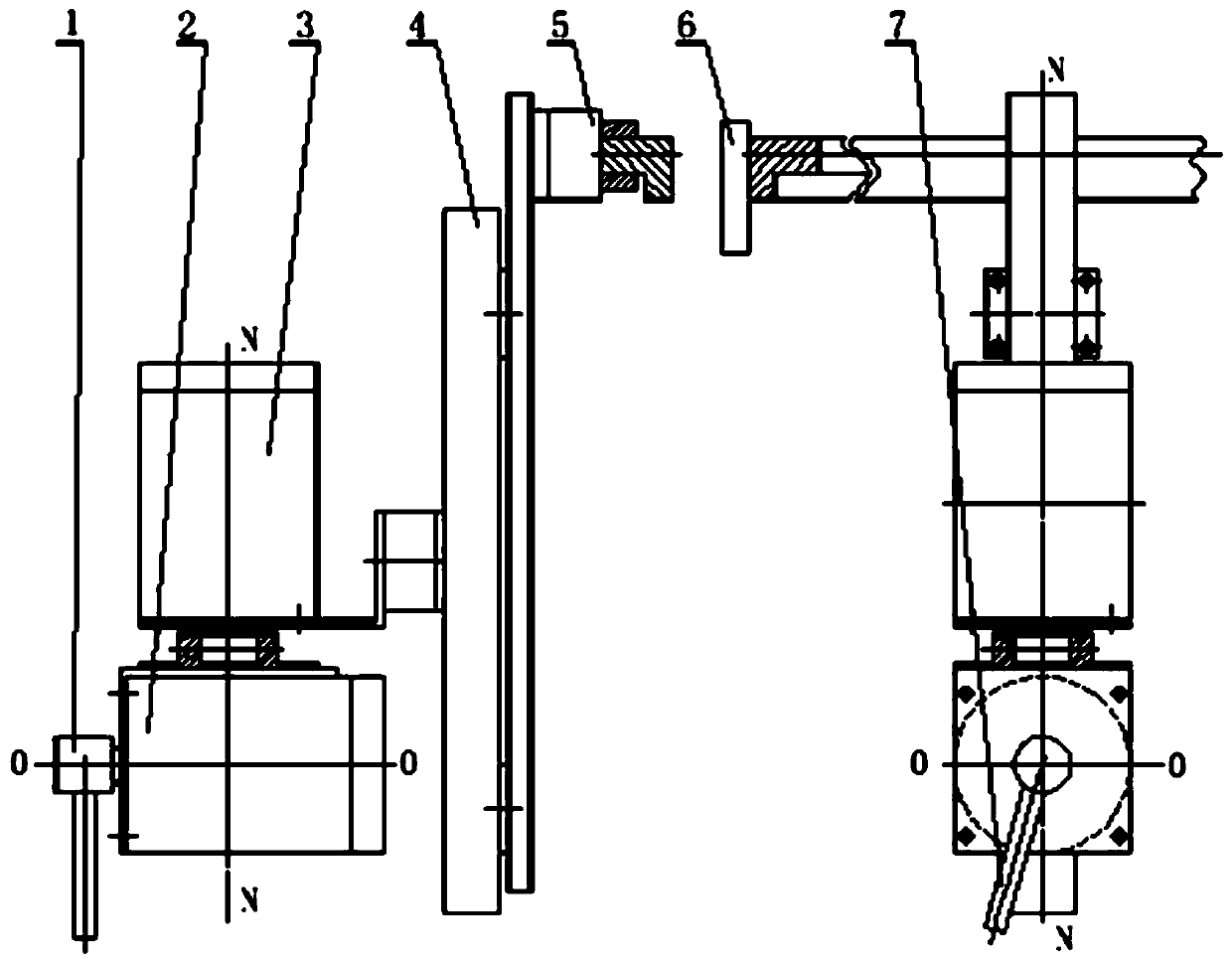
[0025] The present invention can automatically select and control the injection target and injection angle of the nozzle of the cutting fluid follower device through manual preset or automatic search for the target area where the cutting fluid is sprayed, and automatically identify the injection position and autonomously adjust the cutting fluid during the machining process of the machine tool Injection pressure and flow rate, real-time feedback cutting fluid injection target area. The invention utilizes intelligent control technology to independently seek, intelligently control, and independently adjust cutting fluid nozzles for machine tools, and belongs to a three-in-one, finely managed machine tool subsidiary subsystem.

[0026] The present invention avoids the traditio...


PUM


Abstract

The invention provides an intelligent cutting fluid follow-up system for a machine tool. The system comprises a program reading unit, an information processing unit and a cutting fluid follow-up device. The program reading unit reads numerical control program codes of the machine tool and sends the numerical control program codes to the information processing unit. The information processing unitcontrols the cutting fluid follow-up device, adjusts a position and a spraying angle of a cutting fluid nozzle and adjusts spraying pressure and a flow of a cutting fluid according to a preset cuttingfluid spraying area and requirements. Actual use efficiency of the cutting fluid can be improved, cooling and lubricating effects of the cutting fluid on a cutting area are improved, and a service life of a cutting tool is prolonged.

Description

technical field [0001] The invention relates to a machine tool supporting device. Background technique [0002] The existing control method of cutting fluid injection direction is manually operated by the operator. The injection position, injection direction and injection pressure of the cutting fluid are determined based on personal work experience. The management method is relatively extensive. The process cannot be controlled in real time, and the requirements for fine control of the use of cutting fluid cannot be met. [0003] Mainly manifested in the following aspects: [0004] 1) Before processing, the cutting fluid injection direction and injection position are manually controlled by the operator based on experience; [0005] 2) The target position, incident angle and injection pressure of the cutting fluid injection cannot be adjusted in time during the machining process; [0006] 3) There are problems in the existing cutting fluid supply mode, that is, there are ...

Claims


Application Information

Patent Timeline
Patent Type & Authority Applications(China)
IPC IPC(8): B23Q11/10
CPCB23Q11/1038
Inventor 周竞涛陈孟冬李超袁乔
Owner 上海航天壹亘智能科技有限公司
Why Eureka
Try Eureka