
Array substrate, display panel and preparation method thereof

An array substrate and display panel technology, which is applied in the manufacture of semiconductor/solid-state devices, electrical components, and electrical solid-state devices, etc., can solve the problems affecting the display panel display uniformity, poor potential uniformity, and decreased GOA driving ability, etc. The effect of uneven light emission, reducing the left and right borders, and improving the display effect

Active Publication Date: 2019-01-04
WUHAN CHINA STAR OPTOELECTRONICS SEMICON DISPLAY TECH CO LTD
View PDF3 Cites 5 Cited by
  • Summary
  • Abstract
  • Description
  • Claims
  • Application Information

AI Technical Summary

Problems solved by technology

As a result, the left and right borders of the existing display panel (AMOLED panel) are relatively large
If the GOA driving circuit is reduced to reduce the frame width, the GOA driving capability will be reduced; and if the VSS signal line is reduced to reduce the frame width, it will lead to poor uniformity of the VSS potential in the display area of ​​the display panel, and the signal line voltage drop (IR drop) phenomenon is more serious, which affects the display uniformity of the display panel
Therefore, it is a big problem to realize the narrow bezel design of the display panel

Method used


Image

  • Array substrate, display panel and preparation method thereof
  • Array substrate, display panel and preparation method thereof
  • Array substrate, display panel and preparation method thereof

Examples


Embodiment Construction

[0043] The following descriptions of the various embodiments refer to the accompanying drawings to illustrate specific embodiments in which the invention may be practiced. The directional terms mentioned in the present invention, such as [top], [bottom], [front], [back], [left], [right], [inside], [outside], [side], etc., are only for reference The orientation of the attached schema. Therefore, the directional terms used are used to illustrate and understand the present invention, but not to limit the present invention. In the figures, structurally similar elements are denoted by the same reference numerals.

[0044] The present invention aims at the technical problem that the display panel in the prior art has a wide frame, which is not conducive to the design of a narrow frame of the display panel, and this embodiment can solve this defect.

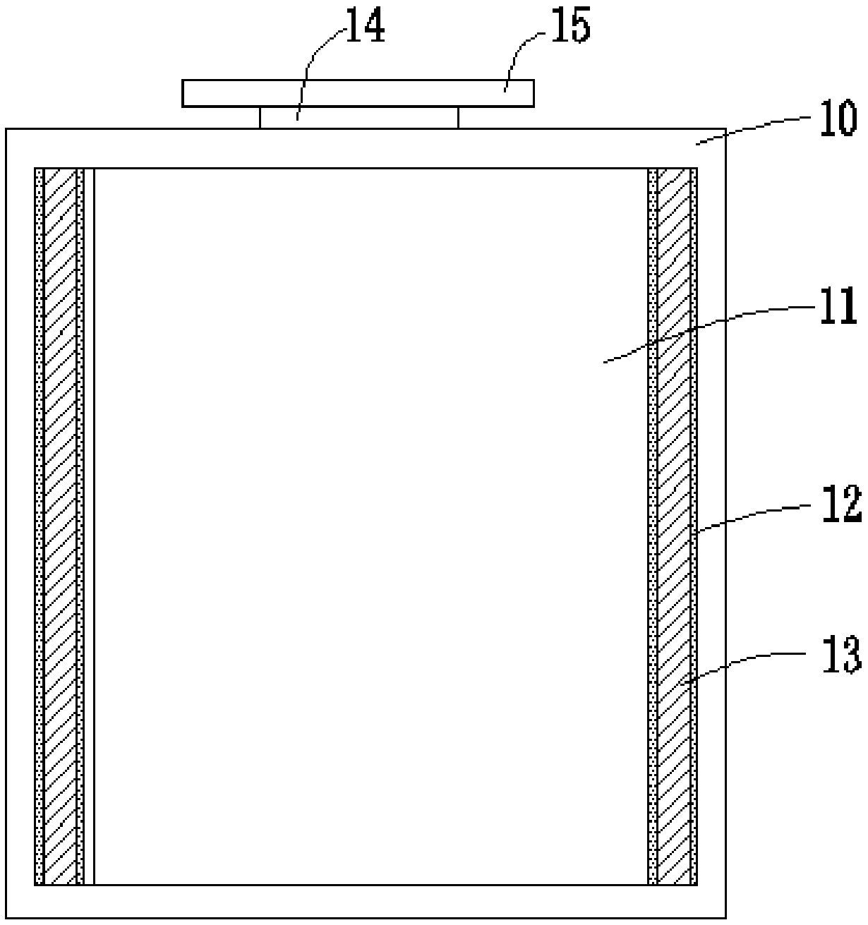
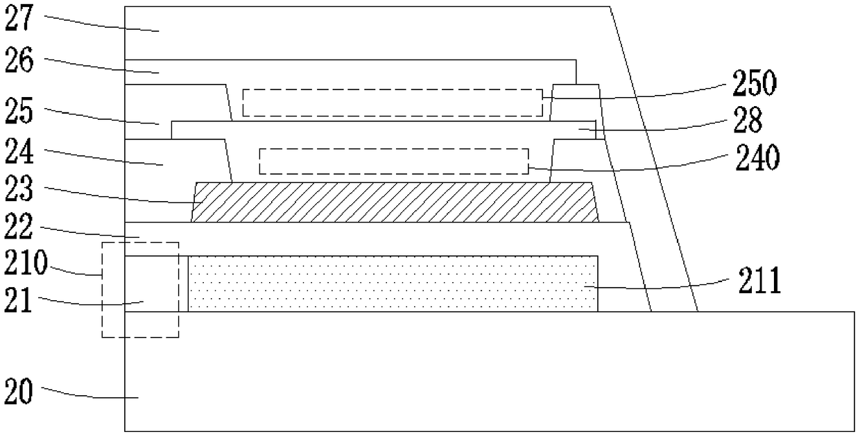
[0045] Such as figure 1 As shown in , it is a schematic structural diagram of the array substrate provided by the embodiment of the...


PUM


Abstract

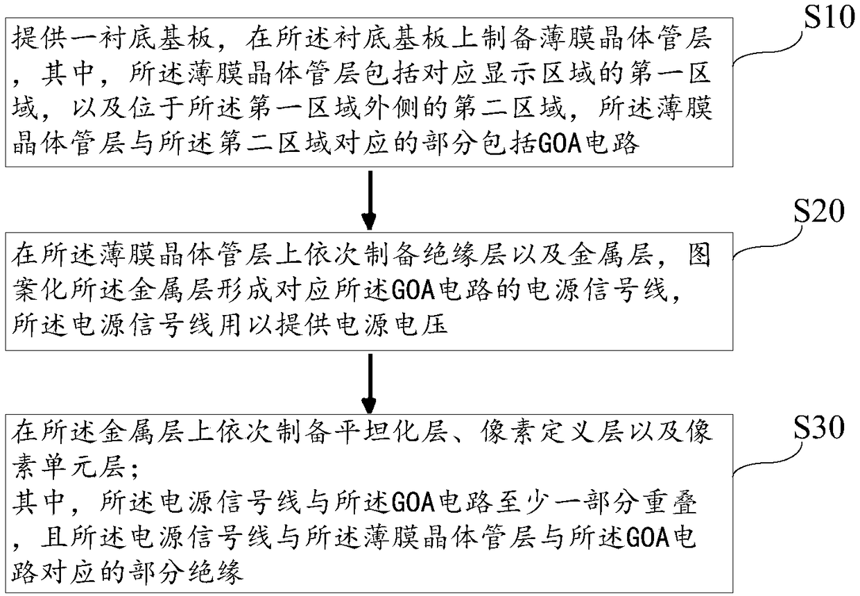
The invention provides an array substrate, a display panel and a preparation method thereof. The array substrate includes a substrate; a thin film transistor layer prepared on the substrate, the thinfilm transistor layer comprising a first region corresponding to a display region and a second region located outside the first region, a portion of the thin film transistor layer corresponding to thesecond region comprising a GOA circuit; An insulating layer prepared on the thin film transistor layer; and a power supply signal line formed on the insulating layer corresponding to the second region to provide a power supply voltage, wherein at least a portion of the power supply signal line overlaps with the GOA circuit, and the power supply signal line is partially insulated from the part ofthe thin film transistor layer corresponding to the GOA circuit.

Description

technical field [0001] The present invention relates to the field of display technology, in particular to an array substrate, a display panel and a preparation method thereof. Background technique [0002] With the development of technology in the display industry, people have higher and higher requirements for display panels. For example, some high-end display panels require a narrow frame design to maximize the effective display area. However, in the design of the existing display panel, a certain width needs to be reserved at the frame position to place other signal lines such as the GOA driving circuit and the VSS signal line. As a result, the left and right borders of the conventional display panel (AMOLED panel) are relatively large. If the GOA driving circuit is reduced to reduce the frame width, the GOA driving capability will be reduced; and if the VSS signal line is reduced to reduce the frame width, it will lead to poor uniformity of the VSS potential in the disp...

Claims


Application Information

Patent Timeline
Patent Type & Authority Applications(China)
IPC IPC(8): H01L27/12H01L27/32H01L21/77
CPCH01L27/124H10K59/122H10K59/131H10K59/1201
Inventor 曾勉
Owner WUHAN CHINA STAR OPTOELECTRONICS SEMICON DISPLAY TECH CO LTD
Learn More