Vector standing wave ratio acquisition method, FPGA and remote radio frequency unit
An acquisition method, a technology of standing wave ratio, applied in the field of communication, can solve the problems of large amount of data, high resource requirements, complex calculation process and so on
- Summary
- Abstract
- Description
- Claims
- Application Information
AI Technical Summary
Problems solved by technology
Method used
Image
Examples
Embodiment 1
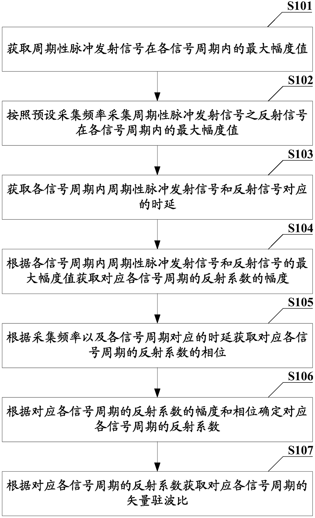
[0034] In order to reduce the resource requirements for obtaining the VSWR and simplify the calculation process, this embodiment provides a method for obtaining the VSWR, see figure 1 , figure 1 A schematic flow chart of a vector standing wave ratio acquisition method provided in this embodiment, including:
[0035] S101: Obtain the maximum amplitude value of the periodic pulse transmission signal in each signal period;
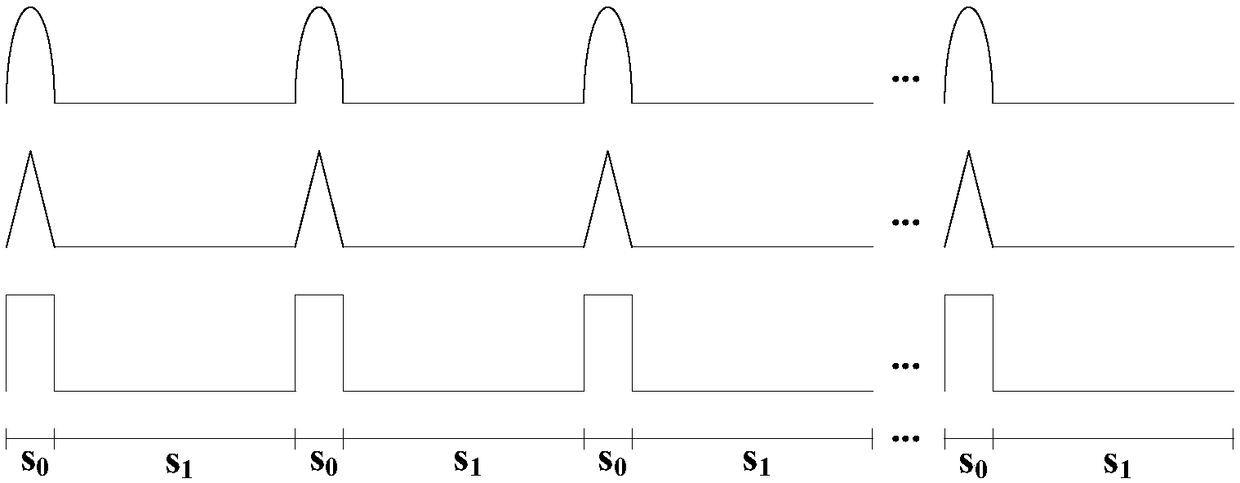
[0036] It is worth noting that, in this embodiment, since the pulse transmission signal is periodic, only the maximum amplitude value in the first signal period can be obtained as the maximum amplitude value of the pulse transmission signal in each signal period It should be understood that, in this embodiment, the maximum amplitude value may also be reacquired once in each signal cycle, so as to ensure the accuracy of the maximum amplitude value obtained in the signal cycle. It should be understood that the acquisition of the maximum amplitude value of the...
Embodiment 2
[0079] In order to reduce the resource requirements for obtaining the vector standing wave ratio and simplify the calculation process, a vector standing wave ratio obtaining device is provided in this embodiment, see Figure 5 , Figure 5 A schematic structural diagram of a vector standing wave ratio acquisition device provided for this embodiment, including a data acquisition module 51 and a processing module 52, wherein:
[0080] The data acquisition module 51 is used to obtain the maximum amplitude value of the periodic pulse transmission signal in each signal period, and collect the maximum amplitude value of the reflected signal of the periodic pulse transmission signal in each signal period according to the preset acquisition frequency; And it is used to obtain the time delay corresponding to the periodic pulse transmission signal and the reflection signal in each signal cycle.
[0081] The processing module 52 is used to obtain the amplitude of the reflection coefficie...
Embodiment 3
[0105] see Image 6 , Image 6 A schematic structural diagram of a remote radio frequency unit provided for this embodiment, including a processor 61 and a field programmable gate array 62, wherein:
[0106] The field programmable gate array 62 is used for sending the periodic pulse transmission signal, and calculates the reflection coefficient of the periodic pulse transmission signal in each signal cycle;
[0107] The processor 61 is used to calculate the vector standing wave ratio of the periodic pulse transmission signal in each signal period according to the reflection coefficient of the periodic pulse transmission signal calculated by the FPGA 62 in each signal period.
[0108] Specifically, the structure of field programmable gate array 62 can refer to Figure 7 As shown, it includes: a signal transmitter 621 , an acquisition processing device 622 , and a reflection coefficient calculation device 623 . in,
[0109] The signal transmitter 621 is used to transmit the ...
PUM
 Abstract
Description
Claims
Application Information
 - R&D
- Intellectual Property
- Life Sciences
- Materials
- Tech Scout
- Unparalleled Data Quality
- Higher Quality Content
- 60% Fewer Hallucinations
Browse by: Latest US Patents, China's latest patents, Technical Efficacy Thesaurus, Application Domain, Technology Topic, Popular Technical Reports.
© 2025 PatSnap. All rights reserved.Legal|Privacy policy|Modern Slavery Act Transparency Statement|Sitemap|About US| Contact US: help@patsnap.com


