
Microphone and manufacturing method thereof

一种制造方法、麦克风的技术,应用在半导体静电换能器、扩音器、静电换能器传声器等方向,能够解决不满足设计要求、影响麦克风信噪比等性能等问题,达到改善容易损坏、提高性能的一致性、提升性能的效果

Active Publication Date: 2019-01-04
SEMICON MFG INT (SHANGHAI) CORP +1
View PDF8 Cites 2 Cited by
  • Summary
  • Abstract
  • Description
  • Claims
  • Application Information

AI Technical Summary

Problems solved by technology

The inclination angle of the side wall of the back hole of the edge part is relatively larger, which makes the overlapping part of the diaphragm and the substrate on the back hole of the edge part may not meet the design requirements, thereby affecting the signal-to-noise ratio of the microphone and other performance

Method used


Image

  • Microphone and manufacturing method thereof
  • Microphone and manufacturing method thereof
  • Microphone and manufacturing method thereof

Examples


Embodiment Construction

[0036] Various exemplary embodiments of the present application will now be described in detail with reference to the accompanying drawings. It should be understood that the relative arrangements of components and steps, numerical expressions and values ​​set forth in these embodiments should not be construed as limiting the scope of the present application unless specifically stated otherwise.

[0037] In addition, it should be understood that, for the convenience of description, the dimensions of the various components shown in the drawings are not necessarily drawn according to the actual scale relationship, for example, the thickness or width of some layers may be exaggerated relative to other layers.

[0038] The following description of the exemplary embodiments is illustrative only and is not intended to limit the application, its application or uses in any way.

[0039] Techniques, methods and devices known to those of ordinary skill in the relevant art may not be disc...


PUM


Abstract

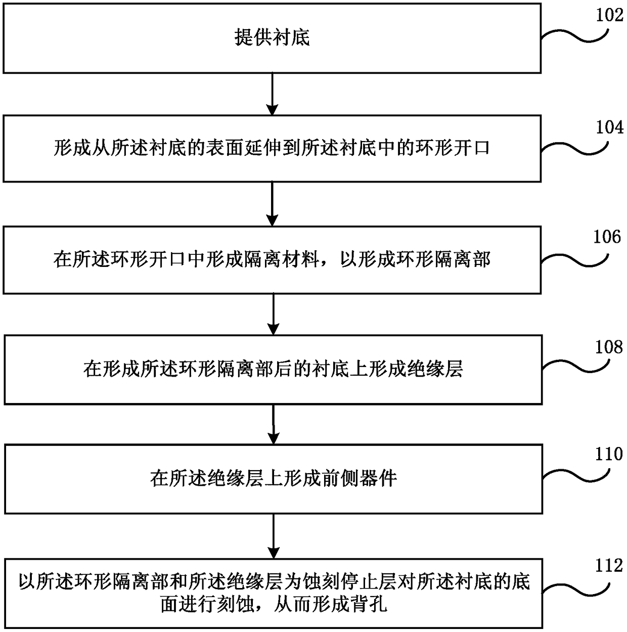
The present invention discloses a microphone and a manufacturing method thereof and belongs to the semiconductor technology field. The method includes the following steps that: a substrate is provided; an annular opening extending from the surface of the substrate to the interior of the substrate is formed; an isolation material is formed in the annular opening, so that an annular isolation portion can be formed; an insulating layer is formed on the substrate on which the annular isolation portion has been formed; a front side device is formed on the insulating layer; and the bottom surface ofthe substrate is etched with the annular isolation portion and the insulating layer adopted as an etch stop layer, so that a back hole can be formed.

Description

technical field [0001] The present application relates to the technical field of semiconductors, in particular to a microphone and a manufacturing method thereof. Background technique [0002] A microelectromechanical system (MEMS) microphone typically includes a substrate, a backhole penetrating through the substrate, and a frontside device overlying the backhole on the substrate. The shape of the back hole is related to the performance of the microphone, therefore, the step of forming the back hole is a key step. [0003] However, the inventors of the present application have found that the back holes formed by the existing manufacturing process have the following problems: [0004] On the one hand, the shape of the back hole formed by the central part and the edge part of the wafer near the corner of the vibrating membrane is inconsistent. The surface of the back hole in the central part near the corner of the vibrating film is a smooth surface, which makes the contact ...

Claims


Application Information

Patent Timeline
Patent Type & Authority Applications(China)
IPC IPC(8): H04R19/04H04R31/00
CPCH04R19/04H04R31/003H04R2201/003H04R2231/001H04R19/005H04R31/00
Inventor 王明军汪新学
Owner SEMICON MFG INT (SHANGHAI) CORP
Learn More