Fixing structure for flying shear blade

A technology of blades and flying shears, applied in the field of fixed structure of flying shears blades, can solve the problems of high frequency of bolt breakage and difficulty in taking out bolts, and achieve the effect of simple and reliable structure, convenient replacement, and ingenious structural design

Pending Publication Date: 2019-01-08
张家港联峰钢铁研究所有限公司
View PDF0 Cites 0 Cited by
  • Summary
  • Abstract
  • Description
  • Claims
  • Application Information

AI Technical Summary

Problems solved by technology

However, in the existing blade fastening structure (the pressing block presses the blade, and the bolt is fixed on the cutterhead body through the pressing block), the bolt size has been finalized. The frequency is high, and it is difficult to remove the broken bolts left in the cutter head, so a new technical solution is urgently needed to solve the above technical problems

Method used


Image

  • Fixing structure for flying shear blade
  • Fixing structure for flying shear blade
  • Fixing structure for flying shear blade

Examples


Embodiment Construction

[0024] In order to deepen the understanding and recognition of the present invention, the present invention will be further described and introduced below in conjunction with the accompanying drawings.

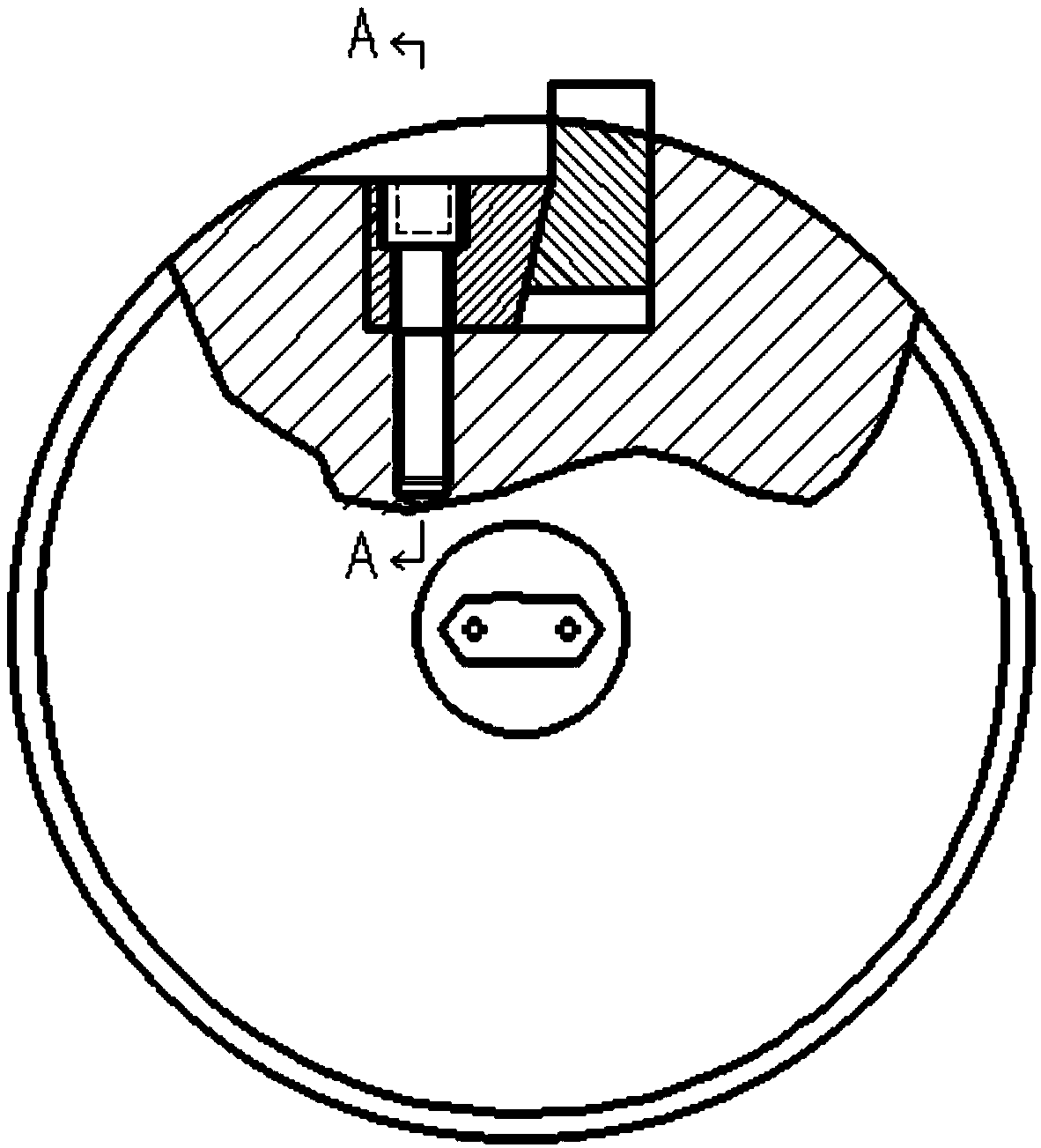
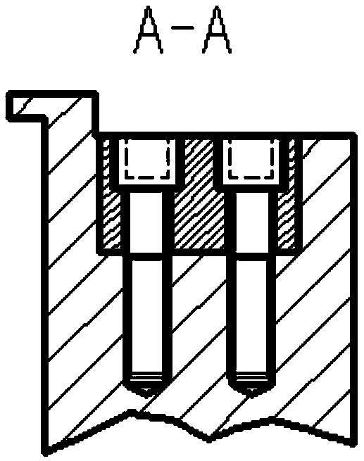
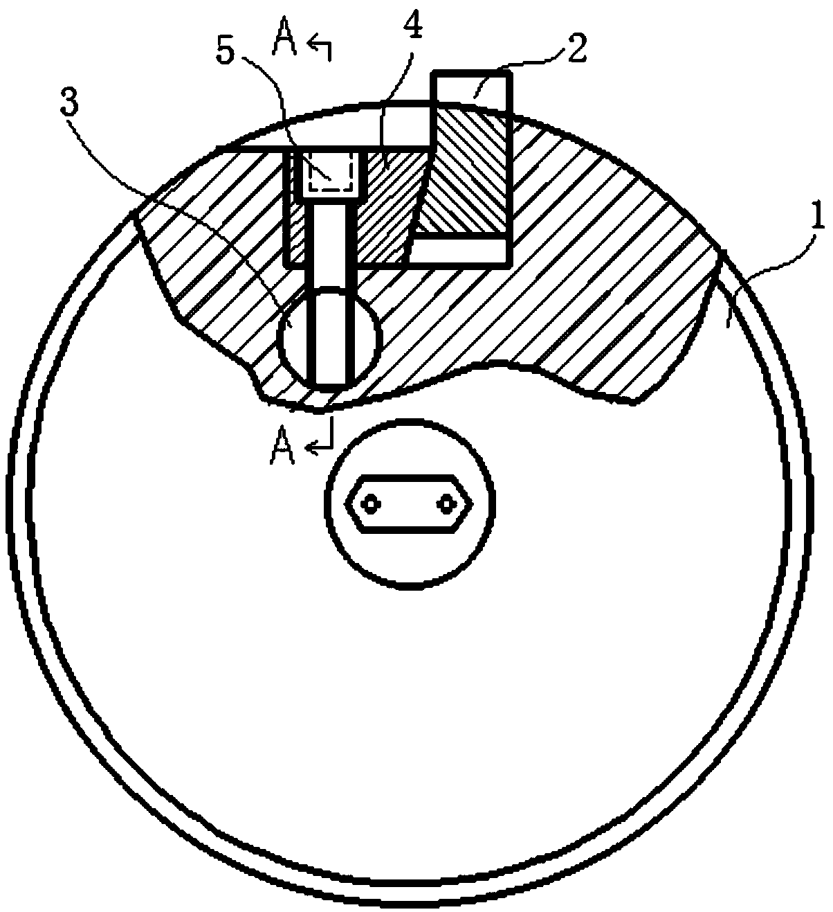
[0025] Such as Figure 3-10 Shown, a kind of fixed frame of flying shears blade comprises cutter head body 1, blade 2, pin shaft 3, briquetting block 4, fastening bolt 5, and described cutter head body 1 is provided with blade 2 and briquetting block 4 The installation notch, the blade 2 is squeezed and positioned in the installation notch of the blade 2 by the pressing block 4, the pin shaft 3 is sleeved on the cutter head body 1, the pin shaft 3 is located directly below the pressing block 4, and the pressing block 4 and pin 3 are fixedly connected by fastening bolt 5.

[0026] Wherein, a pin shaft installation hole is provided on the lower part of the installation notch on the cutter head body 1, and the pin shaft installation hole is a through hole, and the pin shaft 3 is...


PUM


Abstract

The invention relates to a fixing structure for a flying shear blade. The fixing structure comprises a cutter body, the blade, a pin shaft, a pressing block and fastening bolts. The cutter body is provided with an installation notch of the blade and the pressing block, and the blade is extruded and positioned in the installation notch of the blade through the pressing block. The pin shaft is connected to the cutter body in a sleeving manner, the pin shaft is located under the pressing block, and the pressing block and the pin shaft are fixedly connected through the fastening bolts. By means ofthe fixing structure, due to the collaborative effect of the pressing block, the pin shaft, the cutter body and the fastening bolts, the flying shear blade can be safely and effectively fixedly installed for a long time.

Description

technical field [0001] The invention relates to the technical field of steel rolling equipment, in particular to a disc shear mechanism of a finishing mill, and in particular to a fixed structure of flying shear blades. Background technique [0002] In the production process of high-speed wire rods, the temperature of the wire rod head drops after being cooled by passing through water, and there is a phenomenon of blackheads. In order to prevent the blackheads from entering the finishing mill and slipping, it is necessary to install flying shears to cut the wire rod head before the finishing mill. Steel bars, among which the disc shears are widely used due to their advantages of small volume and high cutting precision. However, in the existing blade fastening structure (the pressing block presses the blade, and the bolt is fixed on the cutterhead body through the pressing block), the bolt size has been finalized. The frequency is high, and it is difficult to take out the br...

Claims


Application Information

Patent Timeline
Patent Type & Authority Applications(China)
IPC IPC(8): B23D35/00
CPCB23D35/004
Inventor 向勇陈荣军张林卢正义邓敏
Owner 张家港联峰钢铁研究所有限公司
Why Eureka
Try Eureka