Adjustable positioning milling fixture with uniform clamping force

An adjustable and clamping force technology, applied in positioning devices, clamping, manufacturing tools, etc., can solve problems such as uneven clamping force, scrapped motor casing, etc., to achieve the effect of increasing the force area and not easy to deform

Active Publication Date: 2019-01-08
MAANSHAN XINGLONG FOUNDRY CO LTD
7 Cites 22 Cited by

AI-Extracted Technical Summary

Problems solved by technology

[0005] Aiming at the deficiencies of the prior art, the present invention provides a milling fixture with uniform clamping force and adjustable posit...

Method used

One end of the first splint 7 and the second splint 6 close to each other is fixedly connected with a rubber pad by glue, which increases the friction between the first splint 7 and the second splint 6, and prevents the motor casing from being scratched.
Sectional transmission mechanism comprises transmission rod 21, and transmission rod 21 is positioned at the inside of first connection ring 18 and second connection ring 20, and transmission rod 21 is positioned at the side wall in first connection ring 18 and second connection ring 20. A plurality of evenly distributed spring holes are provided, balls are arranged at the openings of the spring holes, and springs are fixedly connected between the balls and the spring holes, and the inner walls of the first connecting ring 18 and the second connecting ring 20 are provided with The bowl-s...

Abstract

The invention relates to the technical field of motor machining, and discloses an adjustable positioning milling fixture with uniform clamping force. The milling fixture comprises a mounting table, the top of the mounting table is fixedly connected with a connecting block, four evenly distributed sliding holes are formed in the side wall of the connecting block, the four sliding holes communicate,sliding rods are in sliding connection to the inner walls of the four sliding holes, the ends, located in the connecting block, of the four sliding rods are fixedly connected with limiting blocks, limiting grooves are formed in the inner walls of the four sliding holes, the four limiting blocks are in sliding connection with the inner walls of the four limiting grooves, the ends, outside the connecting block, of the four sliding rods are fixedly connected with a first arc clamping plate, and a transmission box is fixedly connected to the bottom of the mounting table. According to the adjustable positioning milling fixture with uniform clamping force, a motor shell is sleeved with the position between a first clamping plate and a second clamping plate, the side wall stress area of the motor shell is increased, clamping force is transmitted by two opposite directions, and when the motor shell is clamped, the shell is not prone to deforming.

Application Domain

Technology Topic

Image

  • Adjustable positioning milling fixture with uniform clamping force
  • Adjustable positioning milling fixture with uniform clamping force
  • Adjustable positioning milling fixture with uniform clamping force

Examples

  • Experimental program(1)

Example Embodiment

[0023] The technical solutions in the embodiments of the present invention will be clearly and completely described below in conjunction with the accompanying drawings in the embodiments of the present invention. Obviously, the described embodiments are only a part of the embodiments of the present invention, rather than all the embodiments. Based on the embodiments of the present invention, all other embodiments obtained by those of ordinary skill in the art without creative work shall fall within the protection scope of the present invention.
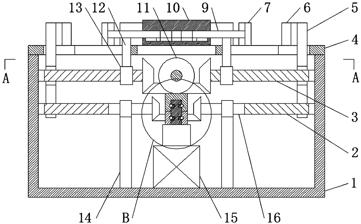
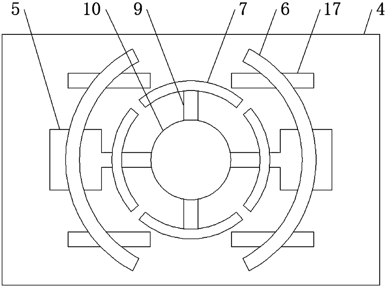
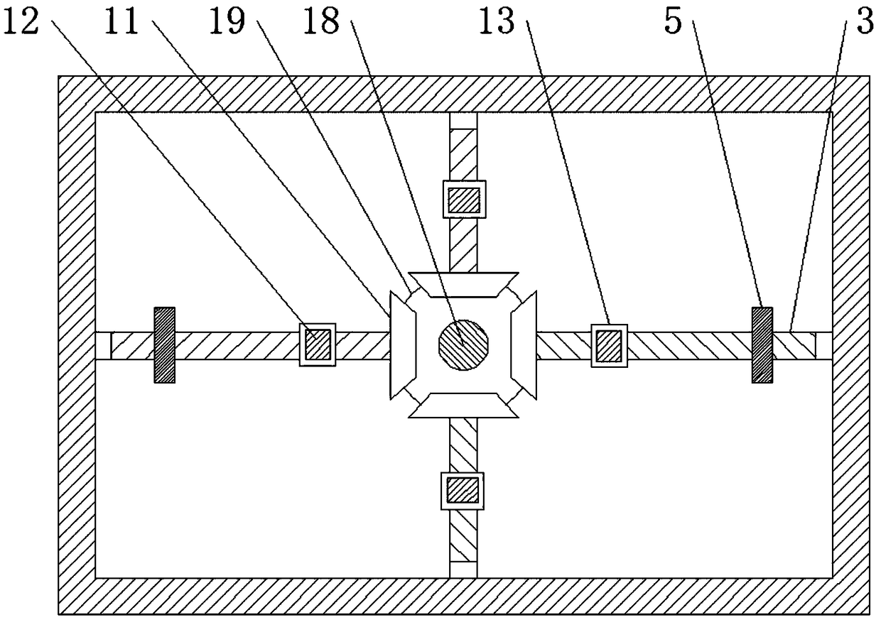
[0024] See Figure 1-4 , A milling fixture with uniform clamping force and adjustable positioning, comprising a mounting table 4, the top of the mounting table 4 is fixedly connected with a connecting block 10, and the side wall of the connecting block 10 is provided with four evenly distributed sliding holes, four sliding The holes are connected, and the inner walls of the four sliding holes are all slidably connected with a sliding rod 9, and the ends of the four sliding rods 9 located in the connecting block 10 are all fixedly connected to a limit block, and the inner walls of the four sliding holes are all provided with a limit slot. The four limit blocks are slidably connected to the inner walls of the four limit slots. The ends of the four sliding rods 9 located outside the connecting block 10 are all fixedly connected with an arc-shaped first splint 7, and the bottom of the mounting table 4 is fixedly connected with a transmission Box 1, the mounting platform 4 is provided with four first slide grooves communicating with the transmission box 1, the four first slide grooves correspond to the four slide bars 9 respectively, and the inner walls of the four first slide grooves all slide Connected to the first connecting rod 12, the upper ends of the four first connecting rods 12 are respectively fixedly connected to the bottom of the four sliding rods 9, the lower ends of the four first connecting rods 12 all extend to the inside of the transmission box 1, and the four The lower end of the first connecting rod 12 is fixedly connected with a threaded sleeve 13, a rotation conversion mechanism is arranged between the four threaded sleeves 13, and the rotation conversion mechanism includes a first bevel gear 19 arranged in a horizontal direction, a first bevel gear 19 is provided with four evenly distributed second bevel gears 11, the four second bevel gears 11 are all vertically arranged, and the four second bevel gears 11 are all meshed with the first bevel gear 19, and the four second bevel gears 11 are The two bevel gears 11 are fixedly connected with the first threaded rod 3 at the axial center of one end far away from each other, and the ends of the four first threaded rods 3 far away from the second bevel gear 11 are all rotatably connected with the inner wall of the transmission box 1 through a rotating shaft. The screw threads of the symmetrically arranged first threaded rods 3 are opposite, the four threaded sleeves 13 are threadedly socketed with the four first threaded rods 3, and two symmetrical second clamping plates 6 are provided above the mounting table 4. The two second splints 6 are both arc-shaped, and the two second splints 6 are respectively located at the two ends of the connecting block 10, and the two second splints 6 are fixedly connected with the fixing plate 5 and the mounting platform 4 at the middle positions of the ends far away from each other. A second chute connected to the first chute is opened on the upper side. The fixed plate 5 is slidably connected to the inner wall of the second chute and extends to the inside of the transmission box 1, and the fixed plate 5 is located at the bottom end of the transmission box 1. A threaded hole is opened, a first connecting ring 18 is fixedly connected to the bottom axis of the first bevel gear 19, and a second connecting ring 20, the first connecting ring 18 and the second connecting ring 20 are arranged below the first connecting ring 18 A segmented transmission mechanism is commonly provided inside the second connecting ring 20, a third bevel gear 22 is fixedly sleeved on the side wall of the second connecting ring 20, and both ends of the third bevel gear 22 are provided with a symmetrical fourth bevel gear 8, two The fourth bevel gears 8 are all arranged in the vertical direction, and they are all meshed with the third bevel gears 22. The two fourth bevel gears 8 are fixedly connected to the second connecting rod 16 at the axial centers of the ends away from each other. The ends of the two connecting rods 16 away from the fourth bevel gear 8 are fixedly connected to the second threaded rods 2, the threads of the two second threaded rods 2 have opposite directions, and the ends of the two second threaded rods 2 are away from the second connecting rod 16 Both through the shaft and the inner wall of the transmission box 1 The two second connecting rods 16 are respectively screwed with threaded holes on the two fixing plates 5, and the inner bottom of the transmission box 1 is fixedly connected with a power source.
[0025] The segmented transmission mechanism includes a transmission rod 21, which is located inside the first connecting ring 18 and the second connecting ring 20. The side walls of the transmission rod 21 located in the first connecting ring 18 and the second connecting ring 20 are provided with multiple A spring hole is evenly distributed. The opening of the spring hole is provided with a ball. A spring is fixedly connected between the ball and the spring hole. The inner walls of the first connecting ring 18 and the second connecting ring 20 are both provided with a ball The matching bowl-shaped groove prevents the first clamping plate 7 and the second clamping plate 6 from squeezing and deforming the motor housing due to high pressure.
[0026] A sliding block 17 is fixedly connected to the edge of the second clamping plate 6 at one end away from the connecting block 10. The mounting table 4 is provided with a third sliding groove matching the sliding block 17, and the sliding block 17 is slidably connected to the inner wall of the third sliding groove. The second clamping plate 6 is restricted to prevent the second clamping plate 6 from deflecting.
[0027] The ends of the first clamping plate 7 and the second clamping plate 6 close to each other are fixedly connected with a rubber pad by glue, which increases the friction between the first clamping plate 7 and the second clamping plate 6 and prevents the motor housing from being scratched.
[0028] The side wall of the second connecting rod 16 is rotatably sleeved with a support ring, the bottom of the support ring is fixedly connected with a support rod 14, and the bottom of the support rod 14 is fixedly connected with the inner bottom of the transmission box 1 to prevent the second threaded rod 2 from bending.
[0029] The first clamping plate 7 and the second clamping plate 6 are each provided with a mounting groove at one end close to each other, and a pressure sensor is embedded in the inner wall of the mounting groove to detect the pressure clamped by the first clamping plate 7 and the second clamping plate 6.
[0030] The power source is a servo motor 15, and a stepping motor can also be used.
[0031] In summary, this milling fixture with uniform clamping force and adjustable positioning, the power source drives the first bevel gear 19 to rotate, the first bevel gear 19 drives the four second bevel gears 11 to rotate synchronously, and the second bevel gear 11 rotates to drive The symmetrical threaded sleeve 13 moves toward or away from each other. The threaded sleeve 13 moves through the first connecting rod 12 to drive the slide bar 9 to move. The slide bar 9 moves to make the four first splints 7 expand outward and contract inward. The source simultaneously drives the third bevel gear 22 to rotate, the third bevel gear 22 drives the second threaded rod 2 to rotate through the fourth bevel gear 8, and the second threaded rod 2 rotates through the fixed plate 5 to drive the second clamping plate 6 to move toward or away from each other. The motor housing is sleeved between the first clamping plate 7 and the second clamping plate 6, so that the force-bearing area of ​​the side wall of the motor housing is increased, and the clamping force is transmitted in two opposite directions, so that the motor housing is not clamped. It is easy to deform. Through the setting of the segmented transmission mechanism, the power source drives the transmission rod 21 to rotate. The transmission rod 21 drives the first connecting ring 18 and the second connecting ring 20 to rotate synchronously through springs and balls. When the first clamping plate 7 clamps the motor When housing, the first clamping plate 7 is blocked to generate resistance, so that the second bevel gear 11, the first bevel gear 19 and the first connecting ring 18 also generate resistance. When the resistance is greater than the force of the spring, the ball is squeezed and caused Shrink into the spring hole, so that the transmission rod 21 rotates in the first connecting ring 18 without driving the first clamping plate 7 to continue to move. When the second clamping plate 6 clamps the motor housing, the transmission rod 21 is in the second The connecting ring 20 rotates inside without driving the second clamping plate 6 to continue to move, thereby preventing the motor housing from being squeezed and deformed.
[0032] It should be noted that the terms "include", "include" or any other variants thereof are intended to cover non-exclusive inclusion, so that a process, method, article or device including a series of elements not only includes those elements, but also includes no Other elements clearly listed, or they also include elements inherent to the process, method, article or equipment. If there are no more restrictions, the element defined by the sentence "including a..." does not exclude the existence of other same elements in the process, method, article, or equipment that includes the element.
[0033] Although the embodiments of the present invention have been shown and described, those of ordinary skill in the art can understand that various changes, modifications, and substitutions can be made to these embodiments without departing from the principle and spirit of the present invention. And variations, the scope of the present invention is defined by the appended claims and their equivalents.

PUM

no PUM

Description & Claims & Application Information

We can also present the details of the Description, Claims and Application information to help users get a comprehensive understanding of the technical details of the patent, such as background art, summary of invention, brief description of drawings, description of embodiments, and other original content. On the other hand, users can also determine the specific scope of protection of the technology through the list of claims; as well as understand the changes in the life cycle of the technology with the presentation of the patent timeline. Login to view more.

Similar technology patents

Classification and recommendation of technical efficacy words

  • Not easily deformed
  • Increase the bearing area

Floating dock with fin stabilizers

ActiveCN108639267AImprove securityIncrease the bearing areaVessel movement reduction by foilsMechanical energy handlingFin stabilizerPiston rod
Owner:ZHEJIANG OCEAN UNIV
Why Eureka
Try Eureka