Brightness adjustment method and device for splicing multiple cameras and portable terminal
What is AI technical title?
AI technical title is built by Patsnap AI team. It summarizes the technical point description of the patent document.
A brightness adjustment and multi-camera technology, applied in the field of image processing, can solve problems such as pixel changes, affecting visual effects, and poor effects
Active Publication Date: 2019-01-08
SHENZHEN ARASHI VISION CO LTD
View PDF6 Cites 3 Cited by
Summary
Abstract
Description
Claims
Application Information
AI Technical Summary
This helps you quickly interpret patents by identifying the three key elements:
Problems solved by technology
Method used
Benefits of technology
Problems solved by technology
The above method is less effective when dealing with images with large brightness differences, and will cause large changes in pixels in the image that are not in the common area, affecting the visual effect
Method used
Image
Click on the blue label to locate the original text in one second.
Reading with bidirectional positioning of images and text.
Examples
Embodiment 1
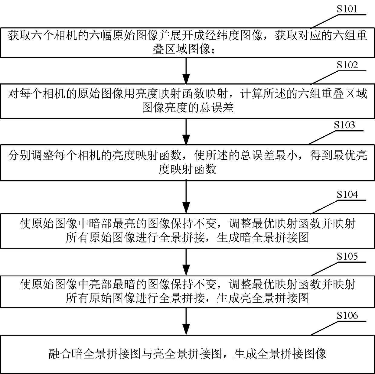
[0077] see figure 1 A brightness adjustment method for multi-camera splicing provided in Embodiment 1 of the present invention includes the following steps:
[0078] S101. Obtain six original images of six cameras and expand them into longitude and latitude images, and obtain corresponding six sets of overlapping area images;
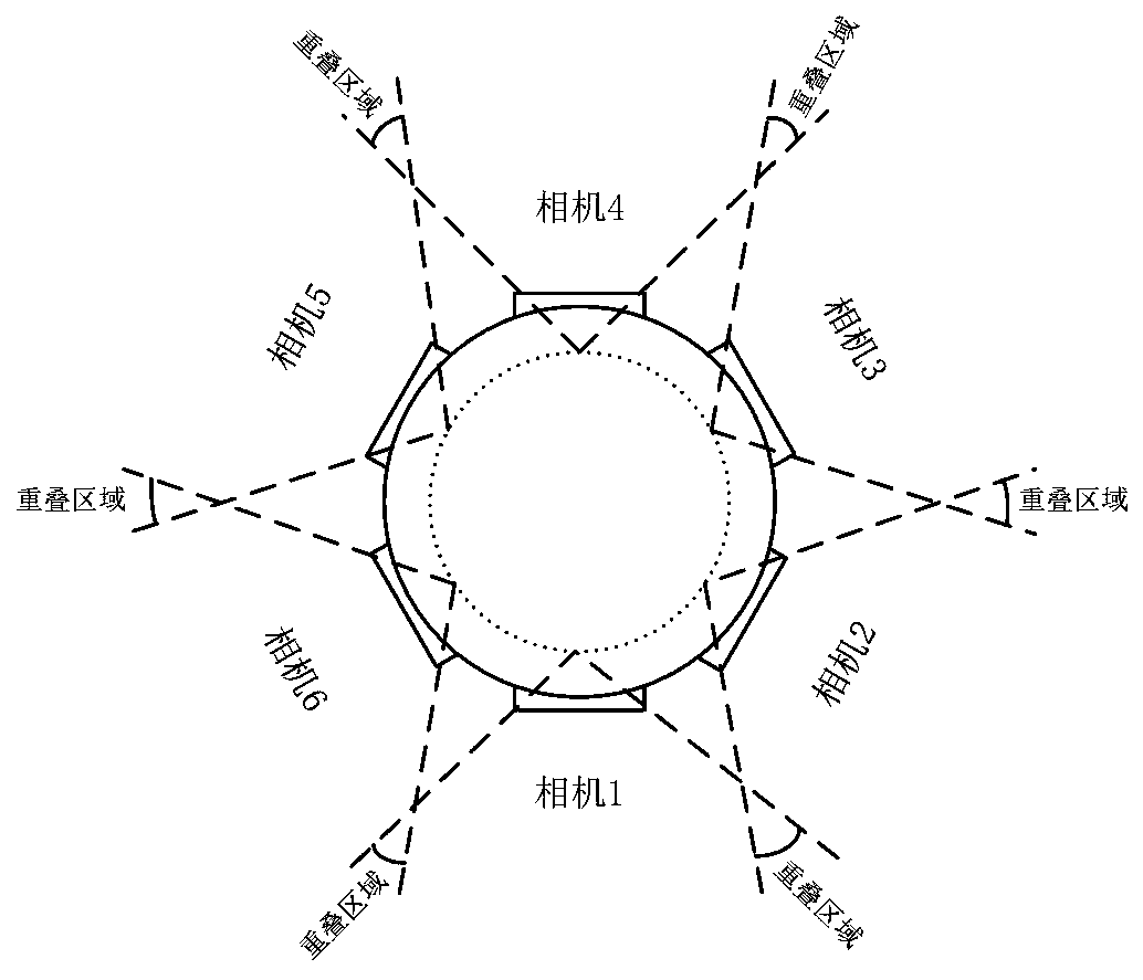
[0079] see figure 2 , the six cameras are six-eye panoramic cameras, and the six original images taken by the six cameras at the same time and independently exposed are six fisheye images, and the images taken by adjacent cameras all have overlapping perspectives;
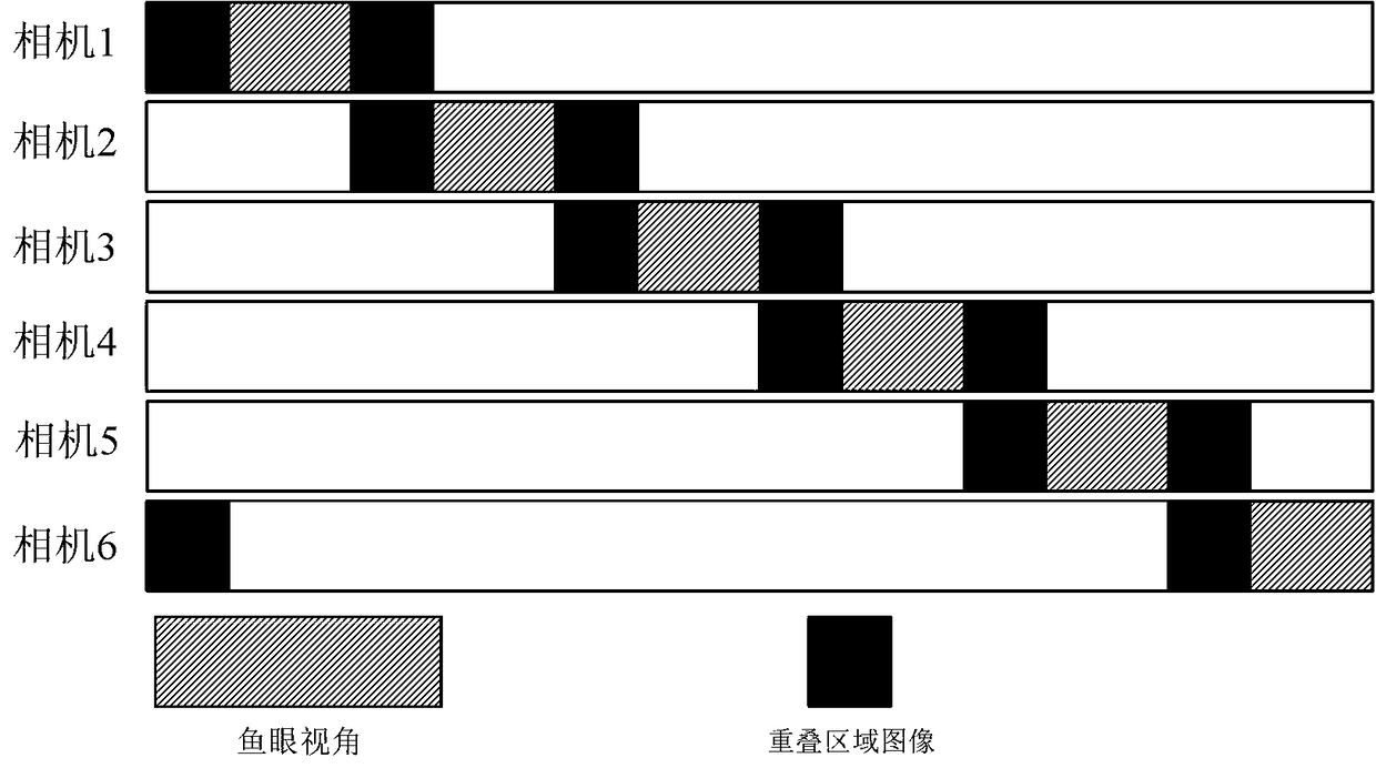
[0080] see image 3 , since each camera has an overlapping angle of view with the adjacent camera, the images captured by the adjacent camera have overlapping areas; six sets of overlapping area images are formed between the latitude and longitude maps of the six fisheye images, Mark the six groups of overlapping area images as sI[i] and rI[i], i=1~6, wherein, sI[i] and rI[i] are a pair ...
Embodiment 2
[0113] see Figure 6 The brightness adjustment device for multi-camera splicing provided in Embodiment 2 of the present invention includes:
[0114] The obtaining module 11 is used to obtain six original images of six cameras and expand them into longitude and latitude images, and obtain corresponding six groups of overlapping area images;
[0115] The calculation module 12 is used to map the original image of each camera with a brightness mapping function, and calculate the sum of the brightness differences of the six groups of overlapping region images as the total error;
[0116] The adjustment module 13 is used to adjust the luminance mapping function of each camera separately, so that the total error is minimized, and an optimal luminance mapping function is obtained;
[0117] Dark panorama mosaic module 14, for keeping the brightest image of the dark part in the original image, adjust the optimal mapping function and map all original images for panorama mosaic, generate...
Embodiment 3
[0133] Embodiment 3 of the present invention provides a computer-readable storage medium. When the computer program is executed by a processor, the steps of the brightness adjustment method for multi-camera splicing as provided in Embodiment 1 of the present invention are implemented.
PUM
Abstract
The invention provides a brightness adjustment method and device for splicing multiple cameras and a portable terminal. The method comprises the following steps of: acquiring original images of six cameras and corresponding six groups of overlapping region images; mapping the original image of each camera with a luminance mapping function to calculate a total error of image luminance of the six groups of overlapping regions; adjusting the brightness mapping function of each camera separately to minimize the total brightness error; adjusting the optimal mapping function and mapping for panoramic splicing to generate the darkest panoramic splicing image with the brightest part and the brightest panoramic splicing image with the darkest part; generating a panoramic mosaic image by fusing a dark panoramic mosaic image and a bright panoramic mosaic image. The technical scheme of the invention realizes the elimination of the brightness difference of the overlapping area by adjusting the brightness mapping function of the camera with independent exposure, keeps the details of the brightness and the darkness of the image unchanged, and better improves the visual effect of the panoramic image.
Description
technical field [0001] The invention belongs to the field of image processing, and in particular relates to a multi-camera splicing brightness adjustment method, device and portable terminal. Background technique [0002] With the continuous development of computer technology and image processing technology, multi-camera image stitching technology has been more and more widely used, such as virtual reality and panoramic images. When obtaining panoramic images, multi-camera image stitching generally requires cameras to shoot from different angles at the same time, and there must be overlapping areas between adjacent images. The image transformation matrix is calculated by using the image matching method through the control point pairs of the same name in the overlapping areas. Thereby splicing into a panoramic image. [0003] In multi-camera panorama stitching, the brightness of the scene in the field of view of each camera is inconsistent. In order to capture more details...
Claims
Application Information
Patent Timeline
Application Date:The date an application was filed.
Publication Date:The date a patent or application was officially published.
First Publication Date:The earliest publication date of a patent with the same application number.
Issue Date:Publication date of the patent grant document.
PCT Entry Date:The Entry date of PCT National Phase.
Estimated Expiry Date:The statutory expiry date of a patent right according to the Patent Law, and it is the longest term of protection that the patent right can achieve without the termination of the patent right due to other reasons(Term extension factor has been taken into account ).
Invalid Date:Actual expiry date is based on effective date or publication date of legal transaction data of invalid patent.

