
A self-adjusting cable tensioning device

A tensioning device, self-adjusting technology, applied in the direction of adjusting/maintaining mechanical tension, etc., can solve the problems of pulling the power rod, collapse, unable to self-adjust, etc.

Active Publication Date: 2019-01-08
STATE GRID JIANGSU ELECTRIC POWER CO LTD TAIZHOU POWER SUPPLY BRANCH +1
View PDF6 Cites 5 Cited by
  • Summary
  • Abstract
  • Description
  • Claims
  • Application Information

AI Technical Summary

Problems solved by technology

However, the existing tensioning mechanisms generally only use elastic structures such as springs to achieve limited tension control, and cannot self-adjust according to actual needs.
However, in actual situations, more complex control methods are often required to ensure the integrity of the functional structure of the equipment or mechanism. There is a solution through fixed connection. Once local strong wind or sudden force is encountered, because the two ends of the cable are fixed, it is easy to cause accidents such as breaking or the collapse of the pole.

Method used


Image

  • A self-adjusting cable tensioning device
  • A self-adjusting cable tensioning device
  • A self-adjusting cable tensioning device

Examples


Embodiment Construction

[0017] The invention will be described in detail below in conjunction with specific embodiments.

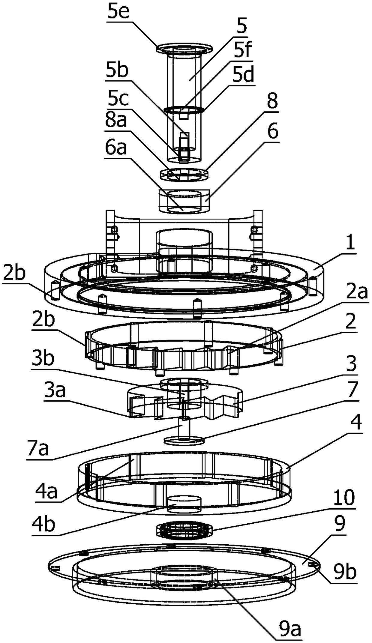
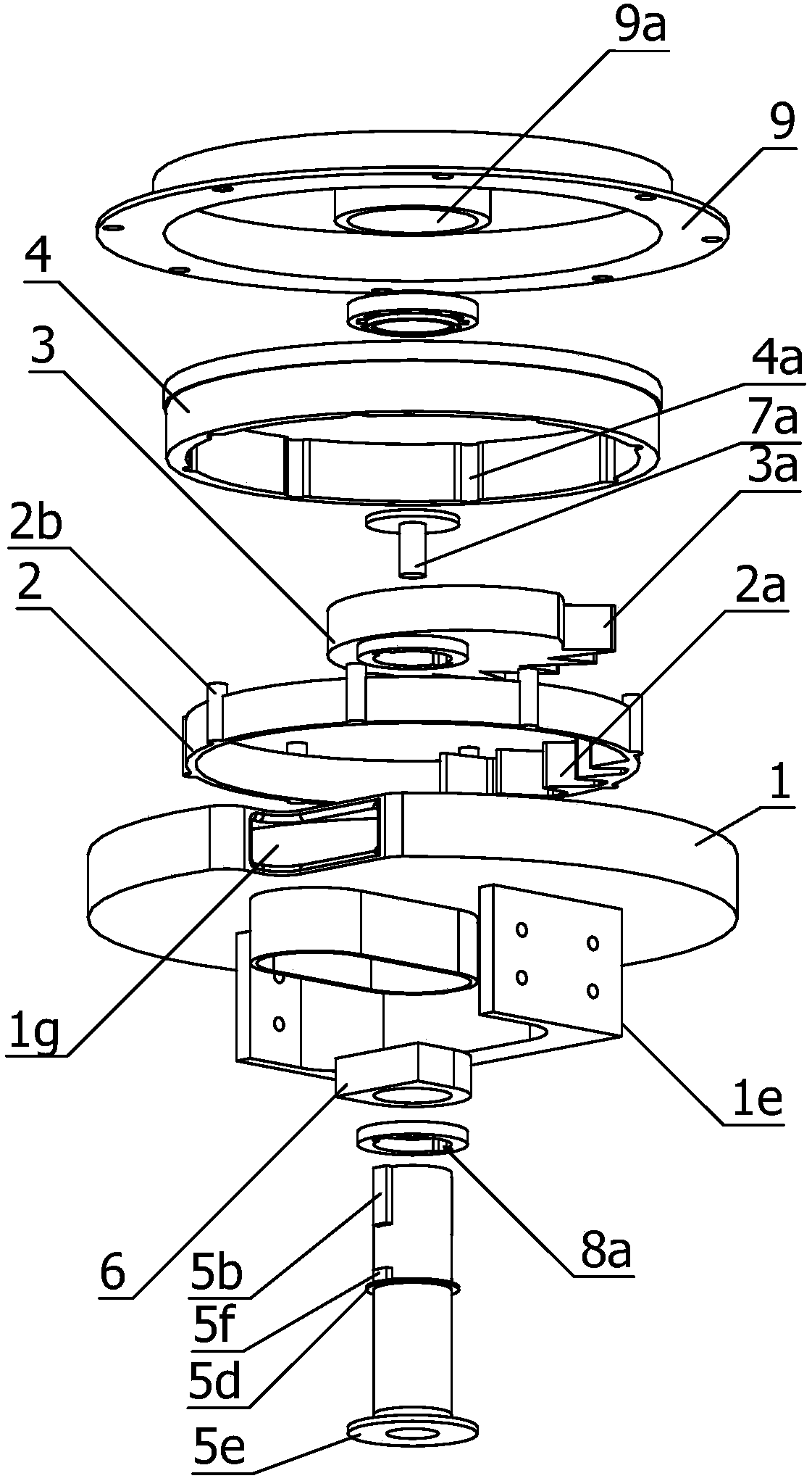
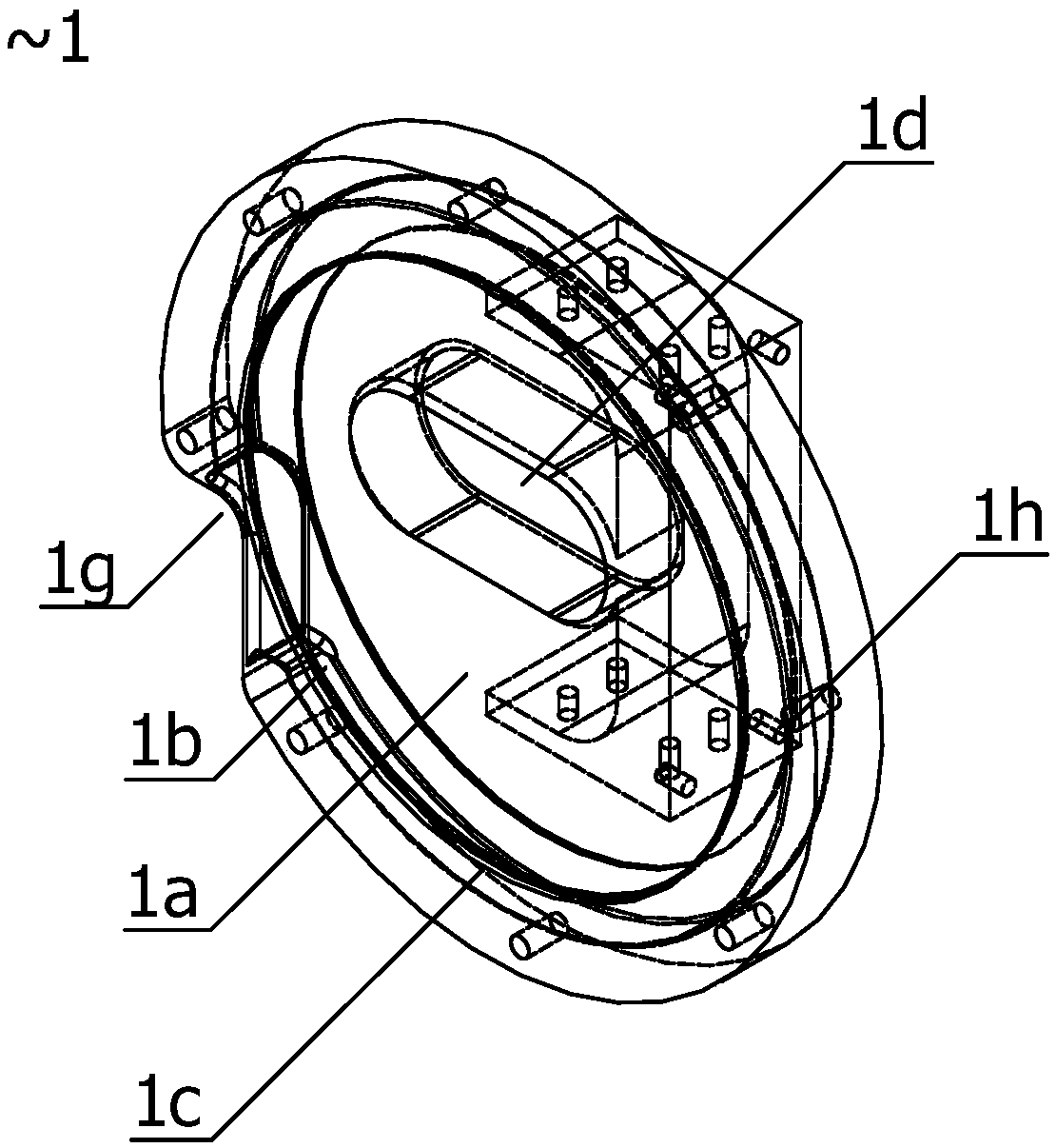
[0018] Such as Figure 1-Figure 4 As shown, a self-adjusting cable tensioning device of the present invention includes a mounting base 1 for connecting various structures, and a cylindrical mounting cavity 1a is provided inside the mounting base 1, and the edge of the mounting cavity 1a extends to the surroundings to install A winding groove 1b is formed inside the seat 1; in this embodiment, for the purpose of saving materials, the shape of the mounting seat in this embodiment is the same as the shape of the mounting cavity, but in fact its shape is based on actual needs and The state of the installation space can be set freely, including setting it as a block shape, a plate shape, etc. One end of the cylindrical installation chamber 1a passes through the installation seat 1 to form an installation opening 1c, and the bottom of the installation chamber 1a is dug with a strip-sh...


PUM


Abstract

The invention belongs to the field of distribution network supporting equipment, in particular to a self-adjusting cable tensioning device. A take-up and take-up distance of that connected fixed electric wire can be set by setting the length of the take-up and take-up cable or the take-up and take-up cable, so that that tension capacity is adjusted, at the same time, the self-adjusting ability isrealized by using the spring to control the rotary drum and using the weight to reset the reset cable, that is, when the tension on the take-up and take-up cable reaches a certain threshold value, thereel is pulled so that the drum, the pawl disengages from the inner ratchet wheel, The drum can rotate freely, so that the take-up and take-up cables are loosened, A tensioning force of that protectmechanism is reduced, After the instantaneous stress disappears, the pawl returns to the original position, and the drum and pawl are connected with the inner ratchet wheel. The gravity of the heavy object causes the return cable to pull and the inner ratchet wheel or the rotary box to rotate so as to recover the cable and keep the original tensioning degree on the electric wire.

Description

technical field [0001] The invention belongs to the field of distribution network supporting equipment, and in particular relates to a self-adjusting cable tensioning device. Background technique [0002] During the installation of cables and various structures of the redistribution network, it is often necessary to use various pretensioning or tensioning and maintaining devices to enable the corresponding structures to achieve specific functions or effects. However, the existing tensioning mechanisms generally only use elastic structures such as springs to achieve limited tension control, and cannot perform self-regulation according to actual needs. However, in actual situations, more complex control methods are often required to ensure the integrity of the functional structure of the equipment or mechanism. There is a solution to fix the connection. In case of local strong wind or sudden force, because the two ends of the cable are fixed, it is easy to cause accidents suc...

Claims


Application Information

Patent Timeline
Patent Type & Authority Applications(China)
IPC IPC(8): H02G7/02
CPCH02G7/02
Inventor 蒋中军张鹏戴永东翁蓓蓓梅鑫
Owner STATE GRID JIANGSU ELECTRIC POWER CO LTD TAIZHOU POWER SUPPLY BRANCH
Learn More