A screw plate system for posterior fixation of the axis

A screw and steel plate technology, which is applied in the field of medical devices, can solve problems such as screw entry and spinal canal invasion, and achieve the effects of reducing the possibility, avoiding infringement, and improving safety and reliability

Pending Publication Date: 2019-01-11
刘观燚
View PDF0 Cites 2 Cited by
  • Summary
  • Abstract
  • Description
  • Claims
  • Application Information

AI Technical Summary

Problems solved by technology

Since the spinous process screw is located in the posterior structure of C2, the screw track completely avoids the transverse foramen, so there is almost no risk of vertebral artery injury in this technique. However, an obvious disadvantage of axial spinous

Method used


Image

  • A screw plate system for posterior fixation of the axis
  • A screw plate system for posterior fixation of the axis

Examples


Embodiment Construction

[0018] The present invention will be described in further detail below in conjunction with the embodiments of the drawings.

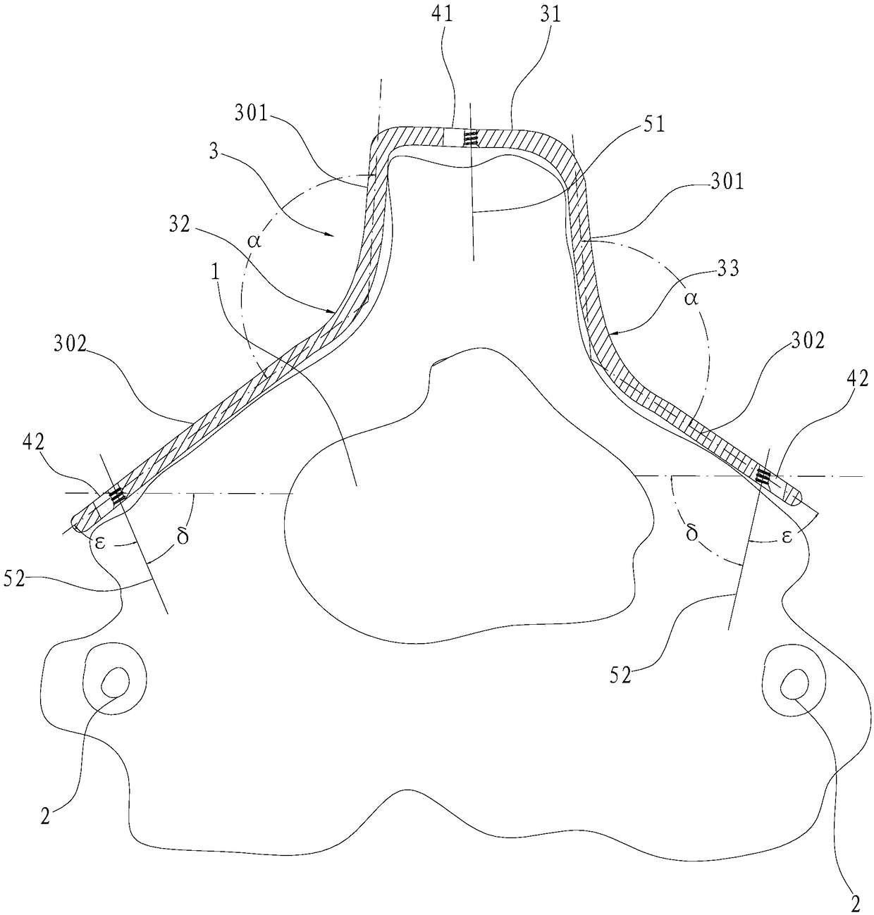
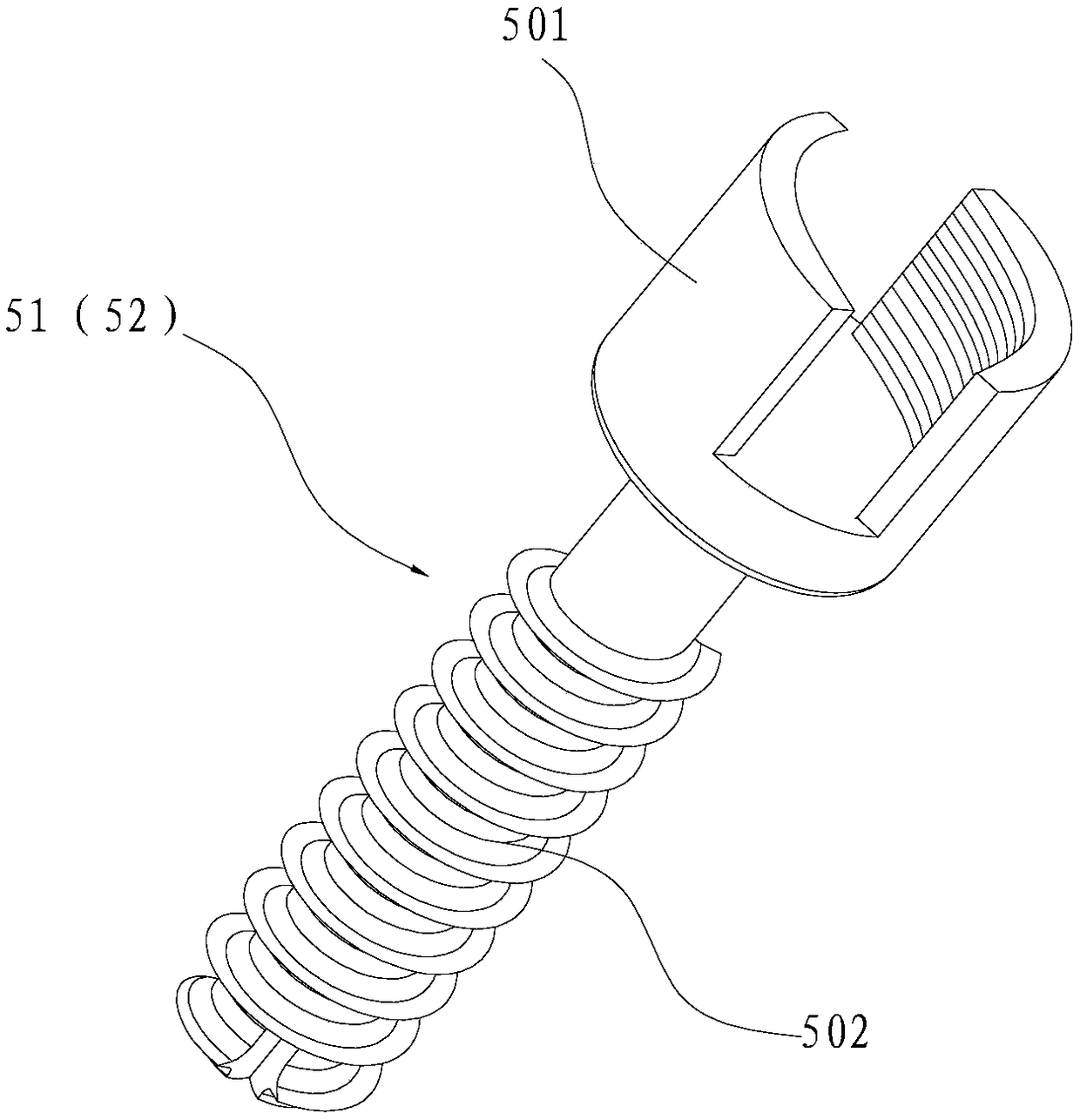
[0019] Such as figure 1 with 2 As shown, a screw plate system for posterior axial fixation includes a spinous process screw 51, an isthmic screw 52, ​​and a spinous process plate 3. figure 1 The central axis of the spinous process screw 51 and each isthmus screw 52 are used to indicate the positions of the two. The above-mentioned spinous process steel plate 3 includes a head end 31 and a first shoulder 32 and a second shoulder 33 respectively arranged on both sides of the head end 31, and the head end 31 matches the anatomical structure of the tip of the spinous process , The first shoulder 32 is matched with the side of the spinous process and the lamina on the side of the tip of the spinous process respectively. In order to enable the spinous process plate 3 of the present invention to be more accurately attached to the fractured surface of the axis, so...


PUM

PropertyMeasurementUnit
Diameteraaaaaaaaaa
Lengthaaaaaaaaaa
Lengthaaaaaaaaaa

Abstract

The present invention relates to a screw plate system for posterior fixation of the axis, including a spinous process screw, an isthmus screw and a spinous process plates. The spinous process plate comprising a head and first and second shoulders disposed on both sides of the head. The head matches the anatomy of the spinous process apex. The first shoulder is matched with the spinous process sideof the spinous process tip and the vertebral lamina, and the second shoulder is matched with the spinous process side of the other spinous process tip and the pushing plate. The head is provided witha first through hole for inserting the spinous process screw, and the first shoulder and the second shoulder are provided with a first through hole for inserting the isthmic screw. The spinous process steel plate can be stably fixed at the corresponding position of the spinous process of the axis, can completely avoid the spinous process screw from being inserted into the vertebral canal, minimizes the possibility of encroaching on the spinal cord, and furthermore can prevent the isthmus screw from encroaching on the vertebral artery.

Description

Technical field [0001] The present invention relates to the field of medical equipment, and in particular to a screw steel plate system used for posterior axial fixation. Background technique [0002] At present, the commonly used axial fixation techniques in clinical practice include C1-2 joint screws, axial pedicle screws, and laminar screws. The above techniques have the risk of damaging the vertebral artery. Among them, because the screw penetrates the four layers of cortical bone fixation of the atlantoaxial joint, [0003] Margerl transarticular screws provide strong fixation, but transarticular screws have high technical requirements and risk of vertebral artery damage. Pedicle screws also have higher technical requirements. The angle, diameter, position of the vertebral artery and transverse foramen of the pedicle may vary. A good screw path must avoid the spinal canal and transverse foramen. In some cases Among them, due to anatomical factors such as too small axial pedi...

Claims


Application Information

Patent Timeline
IPC IPC(8): A61B17/80A61B17/86
CPCA61B17/8004A61B17/8033A61B17/8605A61B17/864
Inventor 刘观燚徐顶立马维虎周雷杰
Owner 刘观燚
Why Eureka
Try Eureka