Clamp for glass mold station transfer

A technology of glass molds and workstations, which is applied in metal processing, manufacturing tools, metal processing equipment, etc., can solve the problems of low degree of generalization and unseen problems, and achieve the goals of improving clamping efficiency, ensuring safety, and saving labor resources. Effect

Pending Publication Date: 2019-01-11
CHANGSHU JIANHUA MOLD TECH
View PDF29 Cites 2 Cited by
  • Summary
  • Abstract
  • Description
  • Claims
  • Application Information

AI Technical Summary

Problems solved by technology

However, there is no technical revelation of the glass mold station transfer fixture that can transfer the glass mold in the clamped state from one station to another station, and as known in the industry, the tooling fixture is used for certain products. It is a special equipment for positioning the workpiece in the manufacturing and / or subsequent processing procedures to meet certain process requirements, and it also usually needs to meet the requirements of no interference during workpiece processing and transfer, and easy operation.
And because this kind of fixture has the exclusive characteristics for a certain workpiece or product, so the degree of generalization is extremely low, and it is often designed and manufactured by the manufacturer of the workpiece or product according to the needs.

Method used


Image

  • Clamp for glass mold station transfer
  • Clamp for glass mold station transfer

Examples


Embodiment Construction

[0019] In order to understand the technical essence and beneficial effects of the present invention more clearly, the applicant will describe in detail the following examples, but the descriptions of the examples are not intended to limit the solutions of the present invention. Equivalent transformations that are only formal but not substantive should be regarded as the scope of the technical solution of the present invention.

[0020] In the following descriptions, all concepts related to directionality or orientation of up, down, left, right, front and back are based on figure 1 The location status is taken as an example, so it cannot be understood as a special limitation on the technical solution provided by the present invention.

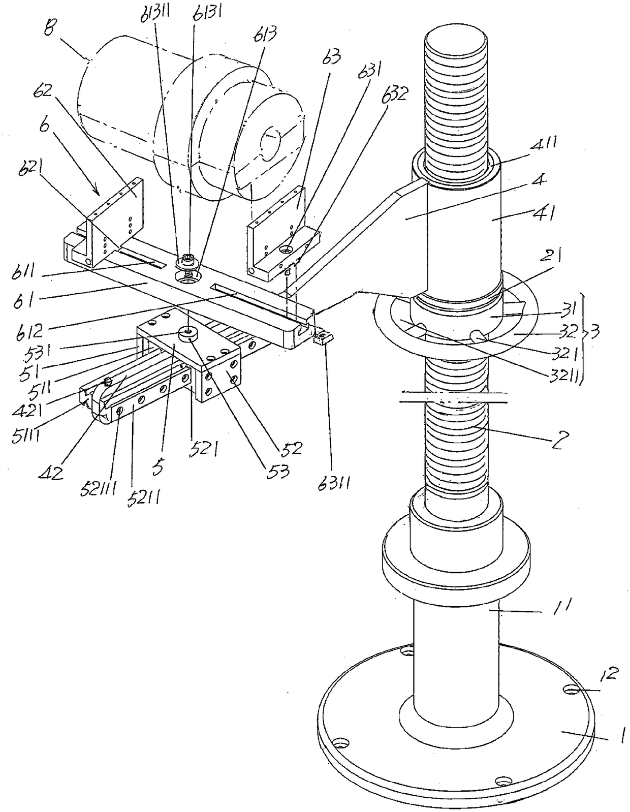
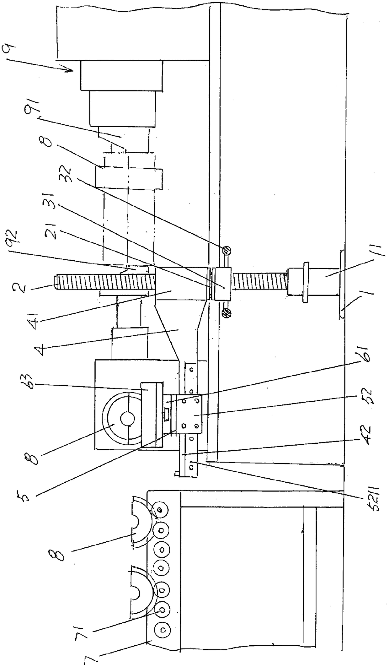
[0021] Seefigure 1 , showing a base 1, a screw fixing sleeve 11 is preferably fixed by welding at the central position of the upward side of the base 1, and the screw fixing sleeve 11 is perpendicular to the base 1; a screw 2 (also can be Call ...


PUM


Abstract

The invention discloses a clamp for glass mold station transfer, and belongs to the technical field of auxiliary facilities for glass mold machining. The clamp for glass mold station transfer comprises a base, a threaded rod, a hand wheel mechanism, a rotating frame, a sliding platform and a glass mold clamping mechanism. A threaded rod fixing sleeve is fixedly arranged in the center of the upwardside of the base and is perpendicular to the base. The lower end of the threaded rod is inserted into the threaded rod fixing sleeve and fixedly arranged in the threaded rod fixing sleeve, and the upper end of the threaded rod upwards stretches. The hand wheel mechanism is arranged on the threaded rod in a threaded matching mode. A rotating frame sleeve is formed at one end of the rotating frame,sleeves the threaded rod in an up-and-down movement mode at the position corresponding to the top of a hand wheel, and is supported by the hand wheel mechanism. The other end of the rotating frame stretches in the direction of being far away from the threaded rod, and a sliding platform guide rail fixing arm is formed at the other end of the rotating frame. The sliding platform and the sliding platform guide rail fixing arm are in sliding fit. The glass mold clamping mechanism is arranged on the sliding platform in a rotating mode. The working intensity is reduced, the clamping efficiency isimproved, the manpower resource is saved, the safety is guaranteed, and energy conservation is embodied.

Description

technical field [0001] The invention belongs to the technical field of auxiliary facilities for glass mold processing, and in particular relates to a clamp for glass mold station transfer. Background technique [0002] The aforementioned glass mold station transfer fixture can also be called "glass mold station ferry (or transition) fixture". As known in the industry, glass molds, especially large-scale glass molds (used to make large-volume glass containers), are very heavy, and an ordinary pair of glass molds weighs 30-40kg. When transferring to the next station, relying on one person's strength is often very reluctant or even can only sigh. Furthermore, as known in the industry, when the last (i.e. the previous) station has completed the processing of the joint surface (also known as the joint surface) of the glass mold, it needs to be transferred to the next (i.e. the latter) station for the glass mold. The outer circle of the mold is processed, for example, the step, ...

Claims


Application Information

Patent Timeline
Patent Type & Authority Applications(China)
IPC IPC(8): B23B15/00
CPCB23Q7/00B23Q2707/003
Inventor 晏庆宝黄后祥苏谦韩志强郁伟峰沈军
Owner CHANGSHU JIANHUA MOLD TECH
Why Eureka
Try Eureka