

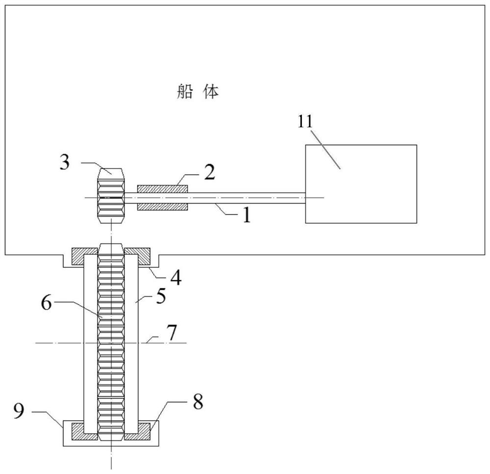
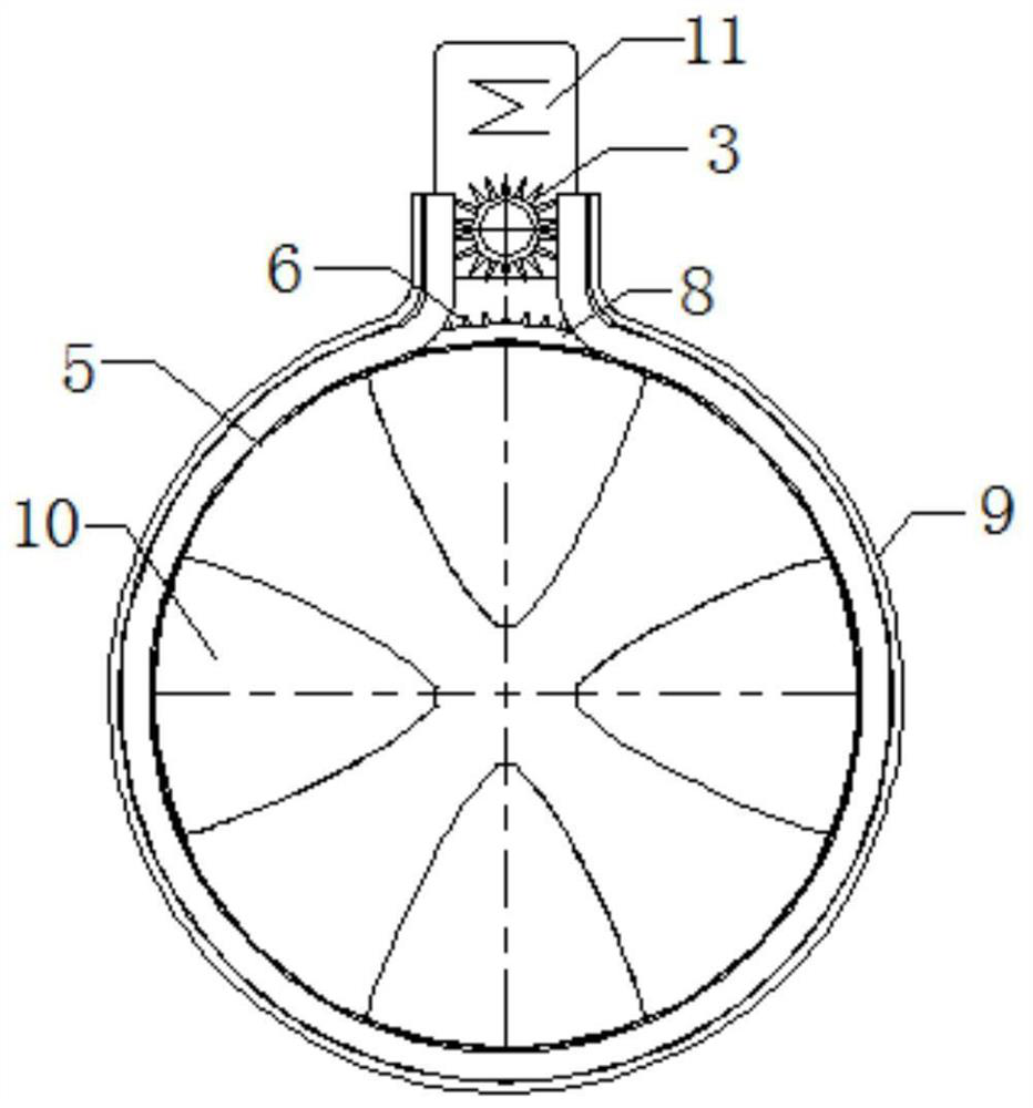
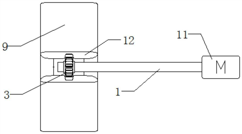
An externally driven marine propulsion system
A propulsion system and external drive technology, applied in the direction of rotary propellers, mechanical gear transmissions, rotary propellers, etc., can solve the problems of affecting airfoil characteristics, small thrust contribution, easy to generate eddy currents, etc., to achieve easy switching, good Hydrodynamic performance, the effect of avoiding local inefficiencies
- Summary
- Abstract
- Description
- Claims
- Application Information
AI Technical Summary
Problems solved by technology
Method used
Image

Examples
Embodiment Construction
[0028] In the following description, numerous specific details are given in order to provide a more thorough understanding of the present invention. It will be apparent, however, to one skilled in the art that the present invention may be practiced without one or more of these details. In other examples, some technical features known in the art are not described in order to avoid confusion with the present invention.
[0029] In order to thoroughly understand the present invention, detailed steps and detailed structures will be provided in the following description, so as to illustrate the technical solution of the present invention. Preferred embodiments of the present invention are described in detail below, however, the present invention may have other embodiments besides these detailed descriptions.
[0030] The purpose of this design is to introduce a new form of propulsion system, which can avoid many disadvantages of the existing technology, so as to obtain better perf...
PUM
 Abstract
Description
Claims
Application Information