Lifting tool of lifting appliance

A lifting tool and technology for lifting equipment, applied in the field of lifting equipment lifting tools, can solve the problems of inconvenient longitudinal beam adjustment, inconvenient longitudinal beam fixing, unstable center of gravity and the like, and achieve the effects of simple structure, high practical performance and convenient operation

Active Publication Date: 2019-01-11
ZHEJIANG KAIDAO HOISTING MACHINERY CO LTD
View PDF7 Cites 5 Cited by
  • Summary
  • Abstract
  • Description
  • Claims
  • Application Information

AI Technical Summary

Problems solved by technology

The utility model takes the lifting ring part as the center, symmetrically arranges a plurality of lifting longitudinal beams on both sides of the lifting ring part, and sets the lifting claw fixture on the lifting longitudinal beam. The hook is hooked with the lifting ring. Under the pulling force of the hook, the hoisting tool of the lifting equipment exerts a balanced pulling force on the equipment in the vertical direction, which avoids damage to the equipment being hoisted. However, this design still has shortcomings. Most of the fixed connections, when the equipment is clamped by the hanging claw clamp, the center of gravity will be unstable and shake if the distance is large, and there is a problem that it is not convenient to adjust the longitudinal beam and it is not convenient to fix the longitudinal beam. Therefore, we propose A hoisting tool for lifting equipment is used to solve the above problems

Method used


Image

  • Lifting tool of lifting appliance
  • Lifting tool of lifting appliance
  • Lifting tool of lifting appliance

Examples


Embodiment

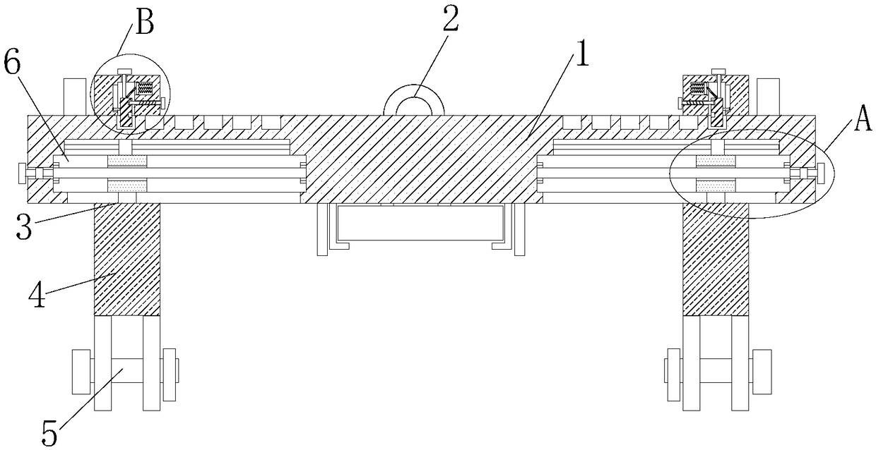
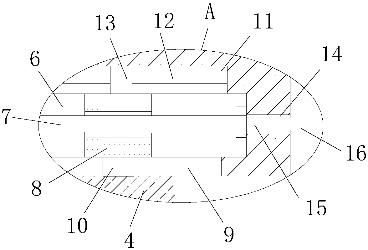
[0025] refer to Figure 1-5 , a hoisting tool for lifting equipment is proposed in this embodiment, including two symmetrically arranged beams 1, two beams 1 brackets are fixedly installed with lifting ring connecting blocks, and the top of the lifting ring connecting blocks is fixedly mounted with lifting rings 2, two Two symmetrically arranged longitudinal beams 4 are slidably installed on the crossbeam 1, and two symmetrically arranged first holes 3 are opened on the longitudinal beam 4, and the crossbeam 1 is slidably connected with the first holes 3, and two longitudinal beams 4 are installed on the longitudinal beam 4. There are two symmetrically arranged cavities 6 on the beam 1, the same screw rod 7 is installed on the inner walls of both sides of the cavity 6, and the sliding seat 8 is installed in the cavity 6. The sliding seat 8 is threadedly set on the corresponding screw rod 7, the bottom inner wall of the cavity 6 is provided with a second hole 9, the bottom of t...


PUM


Abstract

The invention discloses a lifting tool of a lifting appliance. The tool comprises two symmetric cross beams, two cross beam supports are fixedly provided with lifting ring connection blocks, lifting rings are fixedly arranged on the tops of the lifting ring connection blocks, two symmetric longitudinal beams are arranged on the two cross beams in a sliding manner, two symmetric first holes are formed in the longitudinal beams, the cross beams are in sliding connection to the first holes, two symmetric lifting claw clamps are arranged on the longitudinal beams, two symmetric cavities are formedin the cross beams, same lead screws are rotatably arranged on the inner walls of two sides of the cavities, sliding bases are arranged in the cavities in a sliding manner, the sliding bases are arranged on the corresponding lead screws in a thread sleeving manner, second holes are formed in the inner walls of the bottoms of the cavities, and fixed bases are fixedly arranged on the bottoms of thesliding bases. The lifting tool is high in practical performance, simple in structure, convenient to operate, and capable of conveniently adjusting the longitudinal beams and fixing the longitudinalbeams, when equipment is lifted, shaking is not prone to happening, and a user can conveniently use the tool.

Description

technical field [0001] The invention relates to the technical field of electromechanical engineering, in particular to a hoisting tool for lifting equipment. Background technique [0002] During the installation and construction of mechanical and electrical engineering equipment, it is often necessary to hoist the equipment to an installation space with a certain height. After retrieval, the patent document with the authorized announcement number CN204958149U discloses a hoisting tool for hoisting equipment, including lifting ring parts, at least a pair of Mutually parallel hoisting longitudinal beams and a plurality of hoisting claw fixtures; at least one pair of mutually parallel hoisting longitudinal beams is symmetrically arranged on both sides of the hoisting ring part, and the hoisting ring parts are connected with a pair of hoisting longitudinal beams close to the hoisting ring parts, and the hoisting claws are clamped The tool is installed on the hoisting stringer. ...

Claims


Application Information

Patent Timeline
Patent Type & Authority Applications(China)
IPC IPC(8): B66C1/28
CPCB66C1/28
Inventor 谢森涛
Owner ZHEJIANG KAIDAO HOISTING MACHINERY CO LTD
Why Eureka
Try Eureka