

Temperature sensor self-testing device and method
A technology of temperature sensor and self-inspection device, which is applied in the direction of thermometer, measuring device, thermometer test/calibration, etc., which can solve the problems of inability to guarantee train safety, high-efficiency operation, and failure of temperature sensor self-inspection
- Summary
- Abstract
- Description
- Claims
- Application Information
AI Technical Summary
Problems solved by technology
Method used
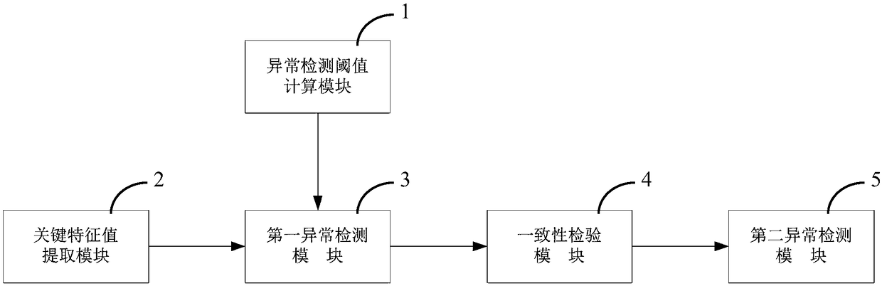
Image

Examples
Embodiment 1
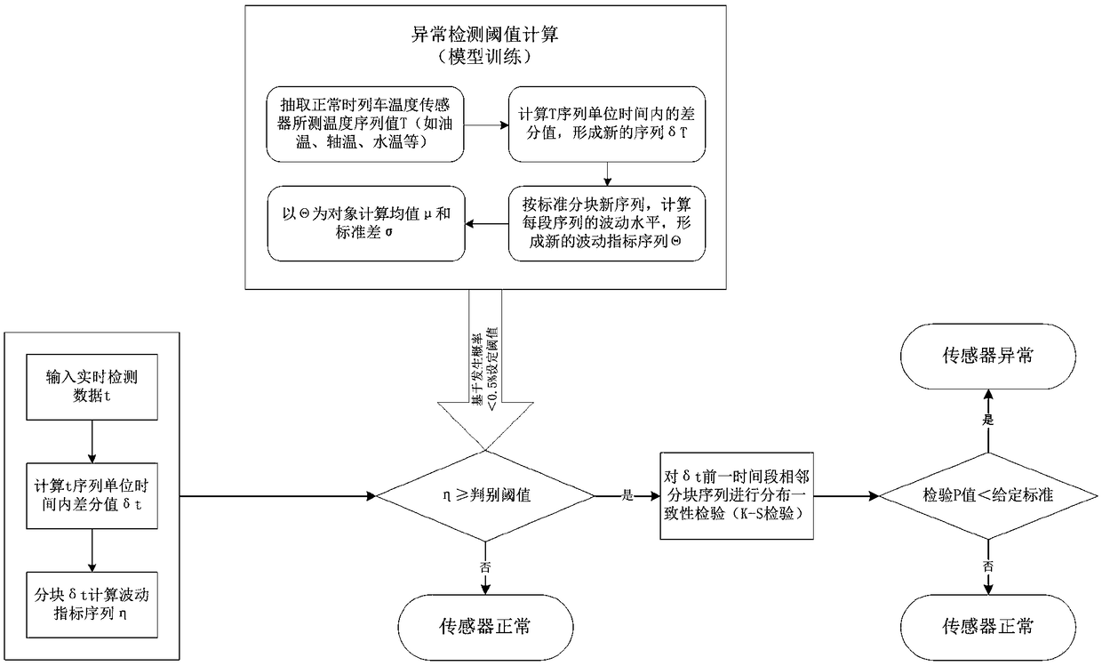
[0079] Through the analysis and research of a large amount of data, it is found that the temperature change of various relevant parts on the train is usually a relatively slow process. That is to say, it is less likely that the temperature will fluctuate greatly in a short period of time, and it is almost impossible for the temperature to drop sharply in a very short period of time. Therefore, based on this consideration, if it is found that the temperature change value fluctuates sharply in a short period of time, and there is a significant difference in the distribution of the change value in a similar period of time, it means that the corresponding temperature sensor (system) is likely to appear exception. Therefore, the specific embodiment of the present invention measures the fluctuation level by the standard deviation of the temperature difference value per unit time, and combines the K-S distribution test method to realize the test and comparison of the temperature diff...
Embodiment 2
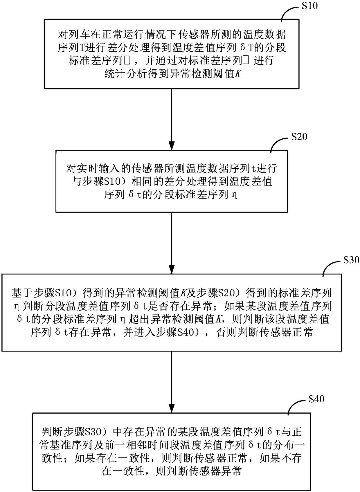
[0107] In this embodiment, since the data used is mainly the time-series temperature data measured by the sensor, when performing real-time abnormal self-inspection, there are relative differences due to the different environments, lines and states of different trains, so it cannot be directly passed The temperature value is judged, so it is necessary to classify and reconstruct the temperature sequence data, establish a difference sequence and calculate the volatility in sections before performing anomaly detection. as attached figure 2 And attached image 3 As shown, an embodiment of a temperature sensor self-test method specifically includes the following steps:
[0108] S10) Carry out differential processing to the temperature data sequence T measured by the sensor under normal operation of the train to obtain the segmented standard deviation sequence Θ of the temperature difference sequence δT, and obtain the abnormal detection threshold K by statistically analyzing the...
PUM
 Abstract
Description
Claims
Application Information