A kind of film shooting wire and method

A film and slider technology, applied in the field of Wia, can solve the problems of controlling self-safety and the inability of actors to save themselves, and achieve the effect of ensuring life safety

Inactive Publication Date: 2020-08-04
BEIJING FILM ACAD
View PDF8 Cites 0 Cited by
  • Summary
  • Abstract
  • Description
  • Claims
  • Application Information

AI Technical Summary

Problems solved by technology

[0003] The practical invention overcomes the above-mentioned deficiencies in the prior art, and provides a film-shooting wire, which is used to solve the problem that actors cannot reasonably control their own safety according to their own situations and that actors cannot save themselves when a steel wire is strangled on the actor's neck.

Method used


Image

  • A kind of film shooting wire and method
  • A kind of film shooting wire and method
  • A kind of film shooting wire and method

Examples


specific Embodiment approach 1

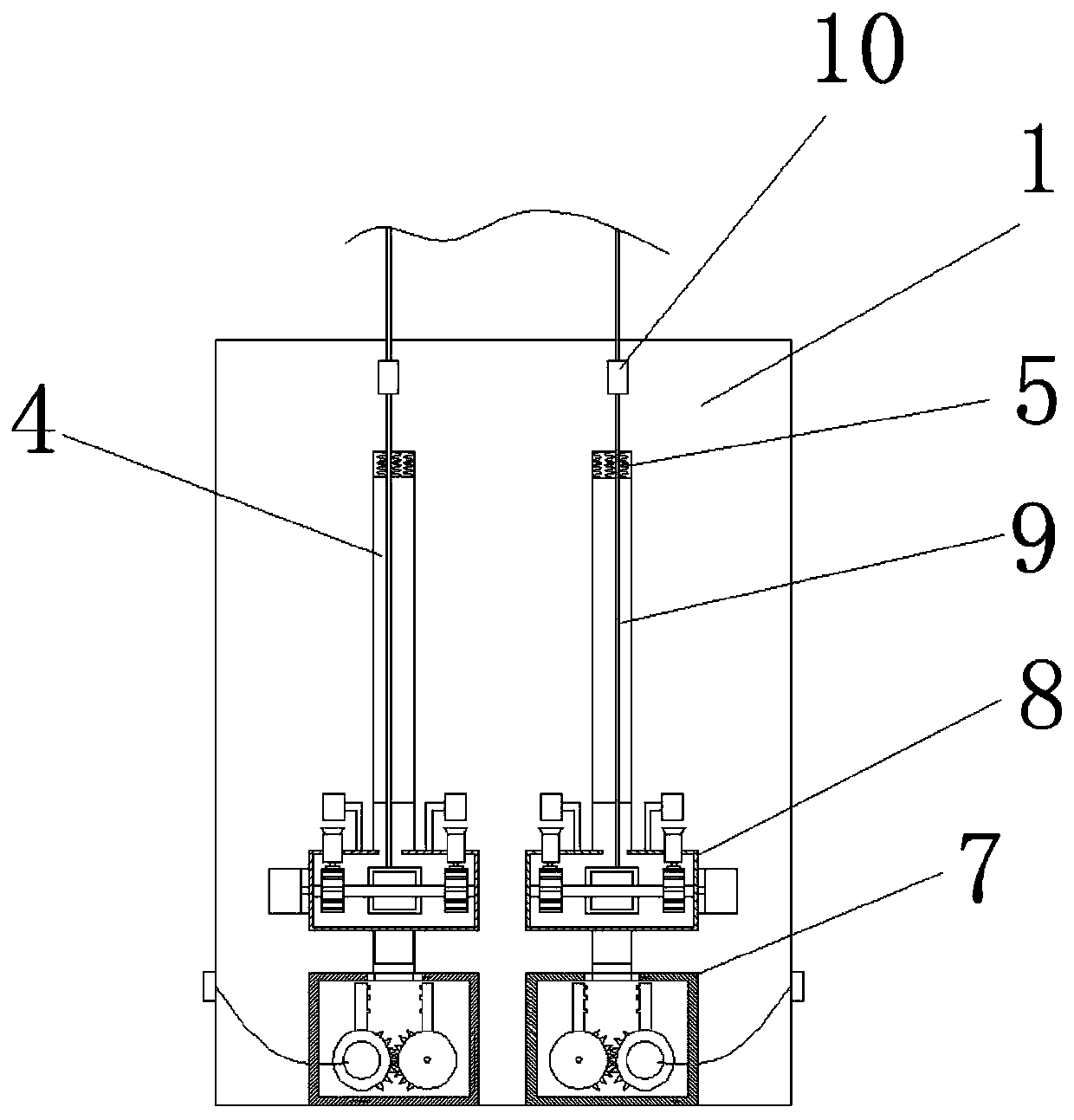
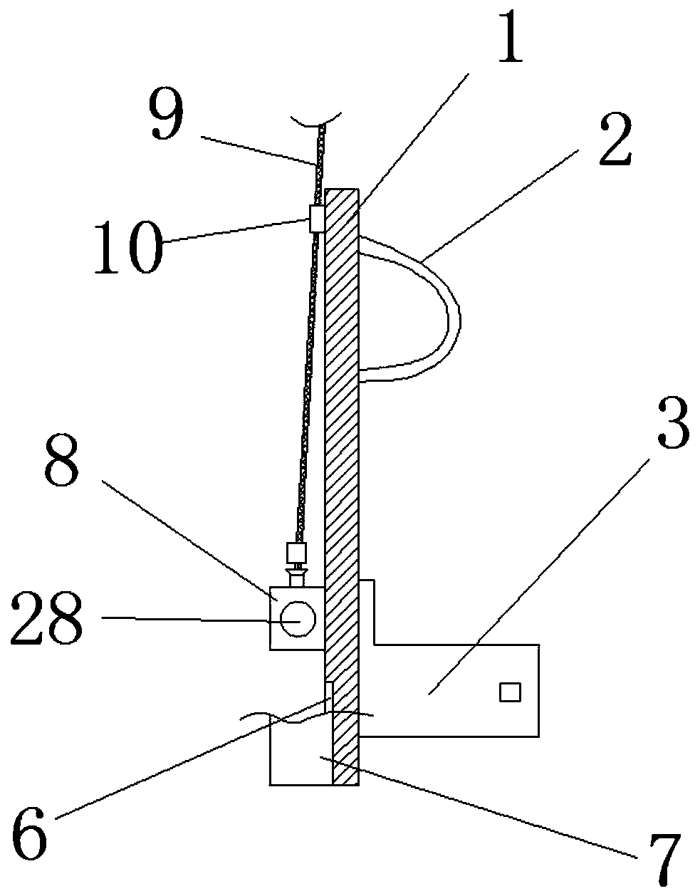
[0037] Such as Figure 1 to Figure 5 As shown, a film shooting wire disclosed in this embodiment includes a backboard 1, a strap 2, a waist belt 3, a shock absorbing spring 5, a fixed box 7, a control device 8, a steel wire 9 and a casing 10; the backboard 1. There is a strap 2 on the front end, a waist belt 3 on the bottom of the strap 2, a T-shaped chute 4 is symmetrically opened on the rear end of the back plate 1, a shock-absorbing spring 5 is arranged on the upper end of the T-shaped chute 4, and a square groove is symmetrically opened on the lower end. 6. There is a fixed box 7 inside the square slot 6. The upper end of the fixed box 7 is connected to the lower end of the control device 8. The control device 8 is symmetrically slid on the T-shaped chute 4. One end of the steel wire 9 is connected to the control device 8, and the other end is through the casing 10;

[0038]Through the function of the back strap 2 and the waist belt 3 provided on the front surface of the ...

specific Embodiment approach 2

[0044] combine Figure 6 As shown, this embodiment is based on the first embodiment, the difference is that the two side walls of the bottom end of the T-shaped slider 29 are provided with limiting grooves 30;

[0045] The bottom side walls of the T-shaped slide block 29 have limit grooves 30, which can be more stably fixed on the fixed box 7 through the limit grooves 30 on the T-shaped slide block 29, fully ensuring the stability, and then ensuring the performance of the actors. It is safe, and can be fixed or separated by human control to achieve the required state.

specific Embodiment approach 3

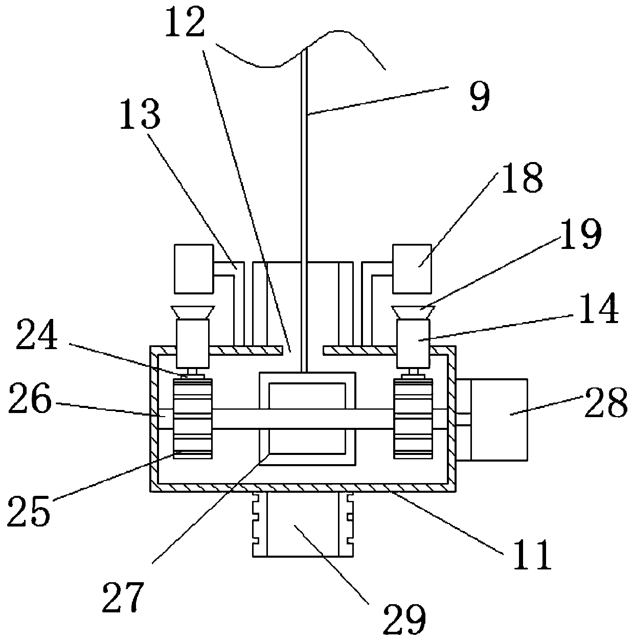
[0047] combine Figure 7 This embodiment is based on the first embodiment, the difference is that the fixed box 7 includes a fixed box 31, a driving incomplete gear 33, a driven incomplete gear 34, a second motor 35 and a limit bar 36; The front end of the fixed box 31 is fixed in the square groove 6, and the upper end of the fixed box 31 has a T-shaped through hole 32, and the driving incomplete gear 33 and the driven incomplete gear 34 are arranged on the fixed box 31 through the rotation of the rotating shaft. Inside, the second motor 35 is arranged on the rear wall of the fixed box body 31, and the output end of the second motor 35 is connected with the driving incomplete gear 33 through the rotating shaft, and the driving incomplete gear 33 and the driven incomplete gear 34 mesh, and the active Both the incomplete gear 33 and the driven incomplete gear 34 are provided with limiting bars 36, and the two limiting bars 36 are arranged parallel and symmetrically;

[0048] Th...


PUM


Abstract

The present invention relates to the technical field of wiring, in particular to a wiring for filming, which includes a backboard, a strap, a belt, a shock absorbing spring, a fixing box, a control device, a steel wire and a casing; the front end of the backboard is provided with a strap, A waist belt is arranged under the back strap, a T-shaped chute is symmetrically opened on the rear end of the back plate, a shock-absorbing spring is arranged on the upper end of the T-shaped chute, and a square groove is symmetrically opened on the lower end, and a fixed box is arranged in the square groove, and the upper end of the fixed box is connected to the The lower end of the control device is connected, and the control device is symmetrically slid on the T-shaped chute. One end of the steel wire is connected to the control device, and the other end passes through the casing. The actor can judge the danger he will face according to his own situation during the shooting process. , You can get out of danger through the control button, or the steel wire strangles the actor's neck, and through the control button, you can realize self-rescue and ensure your life safety.

Description

technical field [0001] The invention belongs to the technical field of wires, and in particular relates to a film shooting wire. Background technique [0002] At present, in many fields such as stage performances and film and television shooting, some soaring action shows also need to use Wia devices. When actors perform hovering or flying movements in the air according to the plot, when they are pulled forward rapidly or the operation is not standardized, it is easy to cause body imbalance. It often happens that the steel wire is strangled on the actor's neck, and the momentary pulling force received by the rope It is very large, and it will pose a great threat to the life safety of actors at this time. During the filming process, due to improper operation of the wire, there were many actors who were "locked" on the spot. Most of the existing coercion used for filming did not have safety self-rescue measures, or most of them had safety measures. Through the control of the...

Claims


Application Information

Patent Timeline
Patent Type & Authority Patents(China)
IPC IPC(8): G03B15/08
CPCG03B15/08
Inventor 李博许晓丹
Owner BEIJING FILM ACAD
Why Eureka
Try Eureka