
Electrical connector and its electrical connector combination

An electrical connector and contact arm technology, applied in the direction of connection, fixed connection, welding/welding connection, etc., can solve the problem of reducing the service life of socket connectors, unfavorable plug connectors and socket connectors, and damage to socket terminals, etc. problem, to achieve the effect of reducing the maximum insertion force, increasing the service life, and reducing signal interference

Active Publication Date: 2020-06-09
DEYI PRECISION ELECTRONIC IND CO LTD PANYU
View PDF5 Cites 0 Cited by
  • Summary
  • Abstract
  • Description
  • Claims
  • Application Information

AI Technical Summary

Problems solved by technology

[0002] An existing socket connector is used for plugging a plug connector with multiple plug terminals downward. The socket connector includes an insulating body and a plurality of socket terminals fixed in the insulating body. Each socket The terminal has a pair of clamping arms. The clamping arms of all the socket terminals are at the same height, and all the plug terminals are at the same height. Therefore, at the beginning of the mutual insertion of the plug terminal and the socket terminal, all the plug terminals need to be simultaneously To overcome the maximum insertion force between the socket terminal and the socket terminal, therefore, it is necessary to apply a large force to insert the plug terminal and the socket terminal when plugging in. This will not only easily damage the socket terminal due to excessive insertion force, thereby reducing the socket connection. The service life of the device is also not conducive to the plugging operation of the plug connector and the socket connector.

Method used


Image

  • Electrical connector and its electrical connector combination
  • Electrical connector and its electrical connector combination
  • Electrical connector and its electrical connector combination

Examples


Embodiment Construction

[0043] In order to facilitate a better understanding of the purpose, structure, features, and effects of the present invention, the present invention will now be further described in conjunction with the accompanying drawings and specific embodiments.

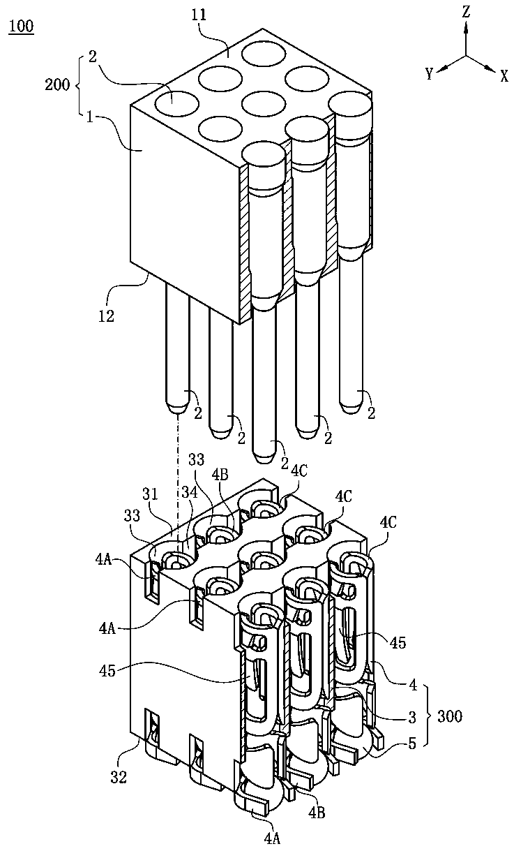
[0044] Such as figure 1 As shown, the electrical connector assembly 100 of the present invention defines a front-rear direction X, a left-right direction Y and a vertical direction Z perpendicular to the front-rear direction X.

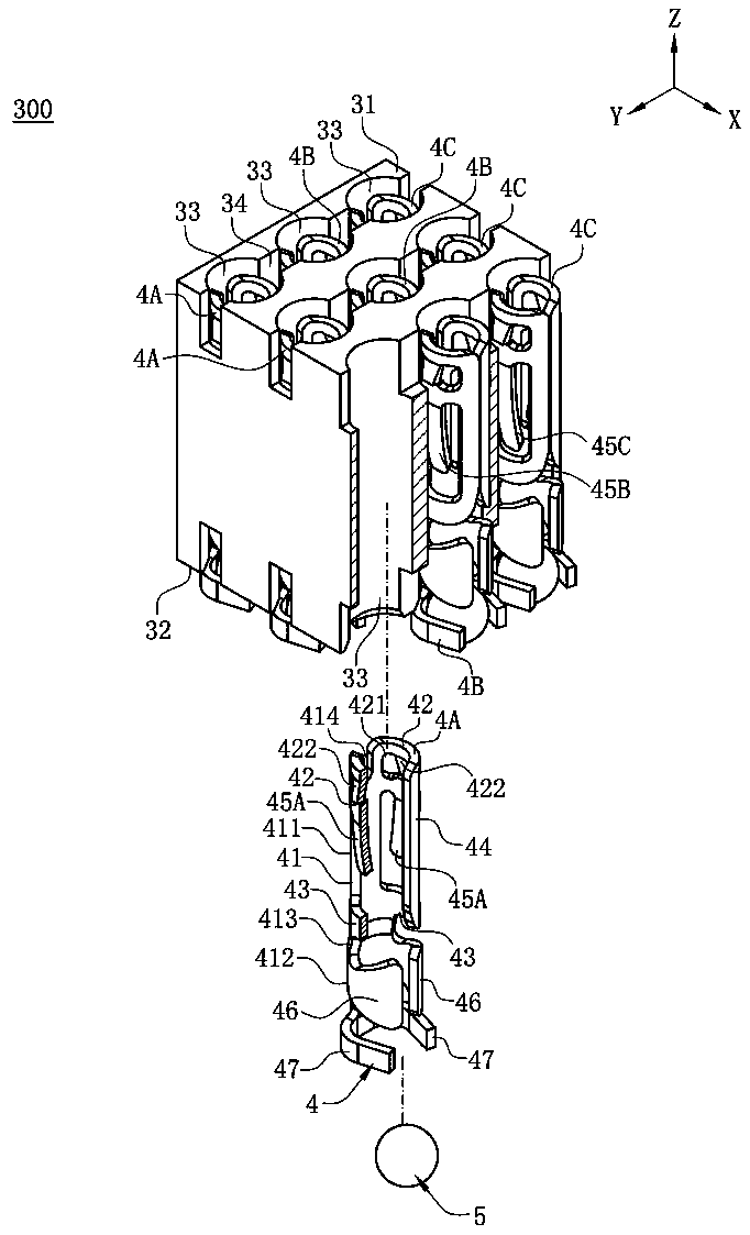
[0045] Such as figure 1 and Figure 7 As shown, the electrical connector assembly 100 of the present invention includes a plug 200 , an electrical connector 300 mated with the plug 200 , and a circuit board 400 welded under the electrical connector 300 .

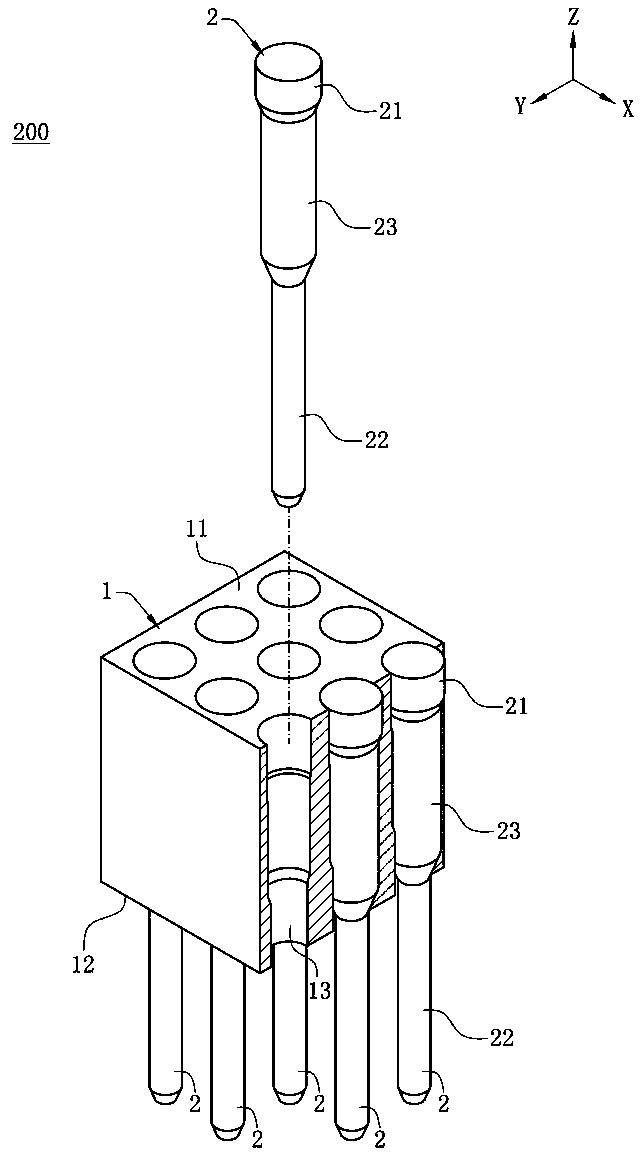
[0046] Such as figure 2 As shown, the plug 200 includes a base 1 and a plurality of pins 2 fixed on the base 1 .

[0047] Such as figure 2 with Figure 5 As shown, the base 1 is made of insulating material, and the base 1 has an opposite top su...


PUM


Abstract

An electrical connector is used for a plug having multiple pins to downward insert therein. The electrical connector includes a body provided with multiple accommodating holes running through an upper surface and a lower surface of the body; and multiple terminals correspondingly accommodated in the accommodating holes. Upper ends of the terminals are located at a same height, and lower ends of the terminals are located at a same height. Each terminal has two contact arms opposite and close to each other. The terminals include a first terminal and a second terminal. The two contact arms of the first terminal and the two contact arms of the second terminal are located at different heights and correspondingly used for the pins to insert downward therein successively. Thus, signal interference between the terminals can be reduced, and a maximum insertion force of the plug inserted into the electrical connector is reduced.

Description

technical field [0001] The invention relates to an electric connector and its combination, in particular to an electric connector with low insertion force and its combination. Background technique [0002] An existing socket connector is used for plugging a plug connector with multiple plug terminals downward. The socket connector includes an insulating body and a plurality of socket terminals fixed in the insulating body. Each socket The terminal has a pair of clamping arms. The clamping arms of all the socket terminals are at the same height, and all the plug terminals are at the same height. Therefore, at the beginning of the mutual insertion of the plug terminal and the socket terminal, all the plug terminals need to be simultaneously To overcome the maximum insertion force between the socket terminal and the socket terminal, therefore, it is necessary to apply a large force to insert the plug terminal and the socket terminal when plugging in. This will not only easily d...

Claims


Application Information

Patent Timeline
Patent Type & Authority Patents(China)
IPC IPC(8): H01R13/11H01R13/6461
CPCH01R13/111H01R13/6461H01R12/57H01R12/716H01R13/193H01R4/02H01R12/58H01R12/87H01R13/04H01R13/11H01R13/40
Inventor 黄常伟
Owner DEYI PRECISION ELECTRONIC IND CO LTD PANYU
Learn More