
An open operation field photography illumination system

A technology of a camera system and a lighting system, applied in the field of surgical appliances, can solve the problems of inconsistent camera framing range and line of sight, asynchrony between the camera system and the light source system, affecting the continuity of surgery, etc. Lightweight, Image Stabilized Effects

Inactive Publication Date: 2019-01-15
吴志明
View PDF8 Cites 0 Cited by
  • Summary
  • Abstract
  • Description
  • Claims
  • Application Information

AI Technical Summary

Problems solved by technology

However, there are many disadvantages in various photography methods nowadays. The traditional tripod support method requires the presence of professional photographers, and many operations by doctors tend to block the exposure field of view. In order to achieve the ideal photography effect, it is necessary to adjust the position and angle of the camera many times, which greatly affects It improves the continuity of the operation and prolongs the unnecessary operation time; the out-of-light boom type also has the problem of visual field obstruction; although the head-mounted camera system can synchronize with the main surgeon's field of view, it is difficult to fix the image due to the shaking of the operator. The viewfinder range and the line of sight range are inconsistent, and the ideal photography effect cannot be fully achieved; the difference between the photography system and the light source system often leads to the inability to obtain complete and clear records of important operations in the dark area of ​​the field of view

Method used


Image

  • An open operation field photography illumination system
  • An open operation field photography illumination system
  • An open operation field photography illumination system

Examples


Embodiment 1

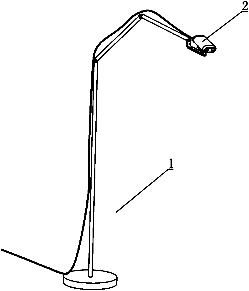
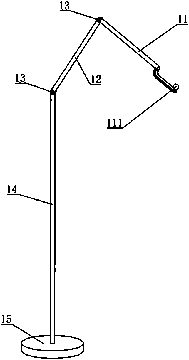
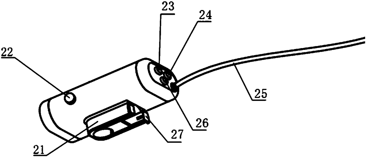
[0029] Such as figure 1 , figure 2 , image 3 and Figure 7 As shown, the present embodiment provides a novel open surgical field of view photography lighting system, including a base 15, a lighting and camera system 2, and a connection plate 27, wherein the base 15 is sequentially connected with the first connecting rod 14, the second connecting rod 12 and the second connecting rod. Three connecting rods 11, the first connecting rod 14 and the second connecting rod 12, the second connecting rod 12 and the third connecting rod 11 are respectively rotatable connections (connected by a rotatable joint 13 in this embodiment, other implementations In the example, other connection methods can also be used, such as hinged); the end of the third connecting rod 11 is provided with a ball head 111, wherein the bottom surface of the lighting and camera system 2 is provided with a U-shaped base 21, and the U-shaped base 21 is provided with a semicircular section. shaped groove, the b...


PUM


Abstract

The invention discloses a novel open operation field photography illumination system, comprising a base, an illumination photography system, and a connecting plate, wherein a connecting rod is arranged on the base, a ball head is arranged at the end of the connecting rod, a U-shaped base is arranged on the bottom surface of the illumination photography system, the U-shaped base has a semicirculargroove in cross section, the ball head is matched with the semicircular groove, and the ball head is rotatably connected with the U-shaped base through the connecting plate; a light source and a camera are arranged at the front end of the illumination photography system. Before use, the ball head is inserted into the semicircular groove of the U-shaped base of the illumination photography system,and the ball head and the U-shaped base are fixed through a connecting plate, the semicircular surface of the ball head is matched with the semicircular groove, so that the arbitrary rotation of thelighting camera system can be realized, the operation operator can fully grasp the situation of the deep operation field in different operation processes, the lamp source and the camera head are juxtaposed, and the advantages of accurate exposure field, high definition, stable image and the like can be achieved under sufficient light sources.

Description

technical field [0001] The present invention relates to the technical field of surgical appliances, and more particularly, to an illumination camera system for an open surgical field of view. Background technique [0002] In contemporary medical teaching, communication, scientific research and telemedicine, the practice of surgery is a crucial part of cultivating an excellent medical talent, especially surgery. However, limited by various factors such as the type of surgery, the number of surgical participants, and the surgical field of view, it is difficult for doctors to fully grasp the various operating methods during surgery. Therefore, surgical camera has become an indispensable tool for medical treatment, teaching, scientific research and telemedicine. Through real-time video recording of the operation, students, doctors and visitors can watch the operation process in real time on a large screen in a classroom away from the operating table, avoiding the risk of surg...

Claims


Application Information

Patent Timeline
IPC IPC(8): A61B90/30A61B90/00
CPCA61B90/30A61B90/361
Inventor 吴志明陈刚许景业茅叶青方倩耿江叶鹏
Owner 吴志明
Learn More