A battery support structure

A battery and structure technology, applied in circuits or fluid pipelines, vehicle components, transportation and packaging, etc., can solve the problems of increased torque of the battery bearing part, deformation of the battery bearing part, restrictions on the shape and size of the battery, etc., to prevent dumping. , The effect of improving shape strength and rigidity, and improving assembly

Active Publication Date: 2019-01-15
HONDA MOTOR CO LTD
View PDF13 Cites 0 Cited by
  • Summary
  • Abstract
  • Description
  • Claims
  • Application Information

AI Technical Summary

Problems solved by technology

Moreover, since the battery carrying part is supported in a cantilever state, there is a danger that a large torque acts on the connecting part of the battery carrying part and the second bracket, and the battery carrying part is deformed due to the torque, thereby making it impossible to keep the battery stable
[0005] In addition, when the height of the battery increases, the center of gravity of the battery becomes higher, and the moment acting on the battery mounting part becomes larger, so the shape and size of the battery are also restricted.

Method used


Image

  • A battery support structure
  • A battery support structure
  • A battery support structure

Examples


Embodiment Construction

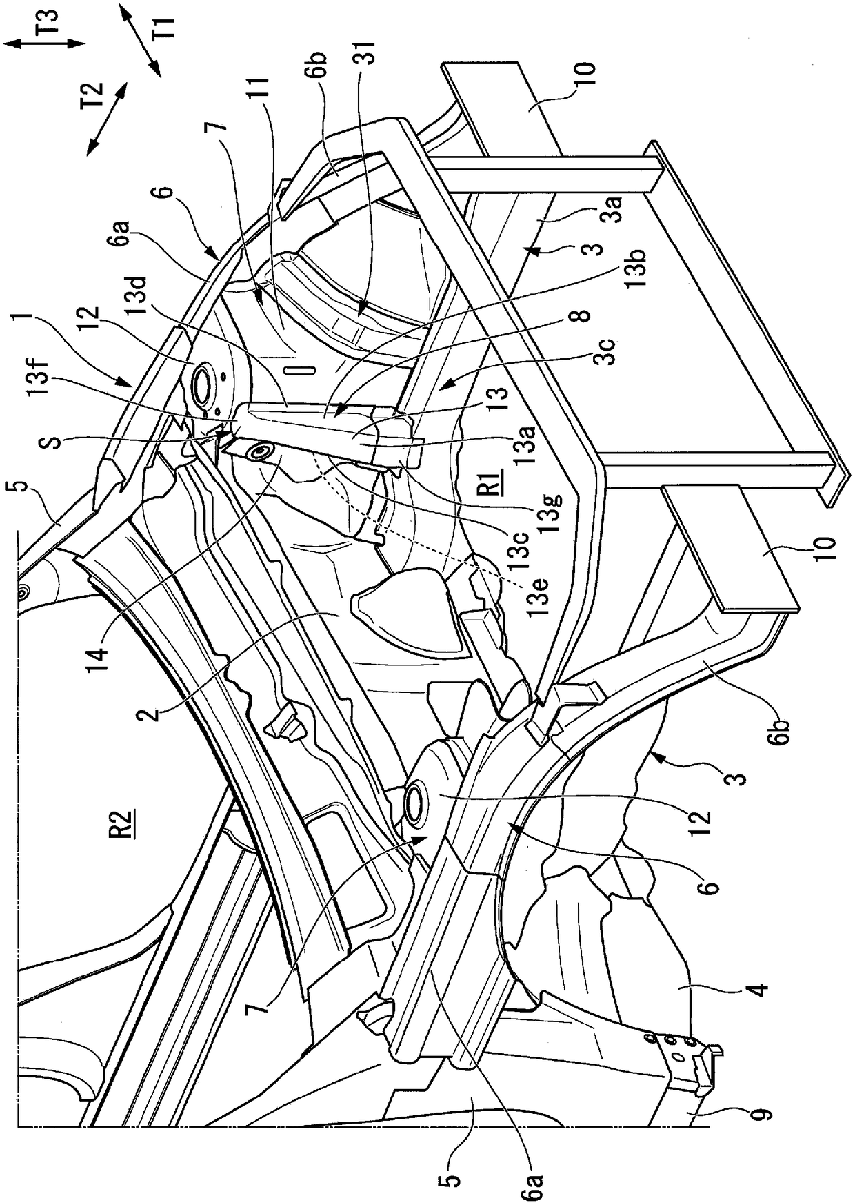
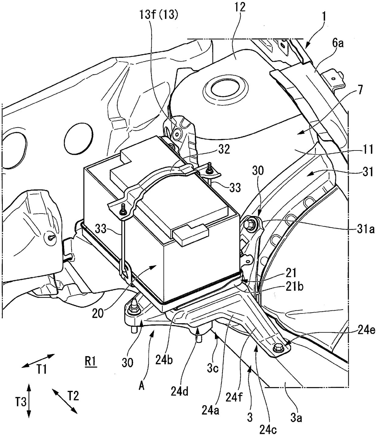
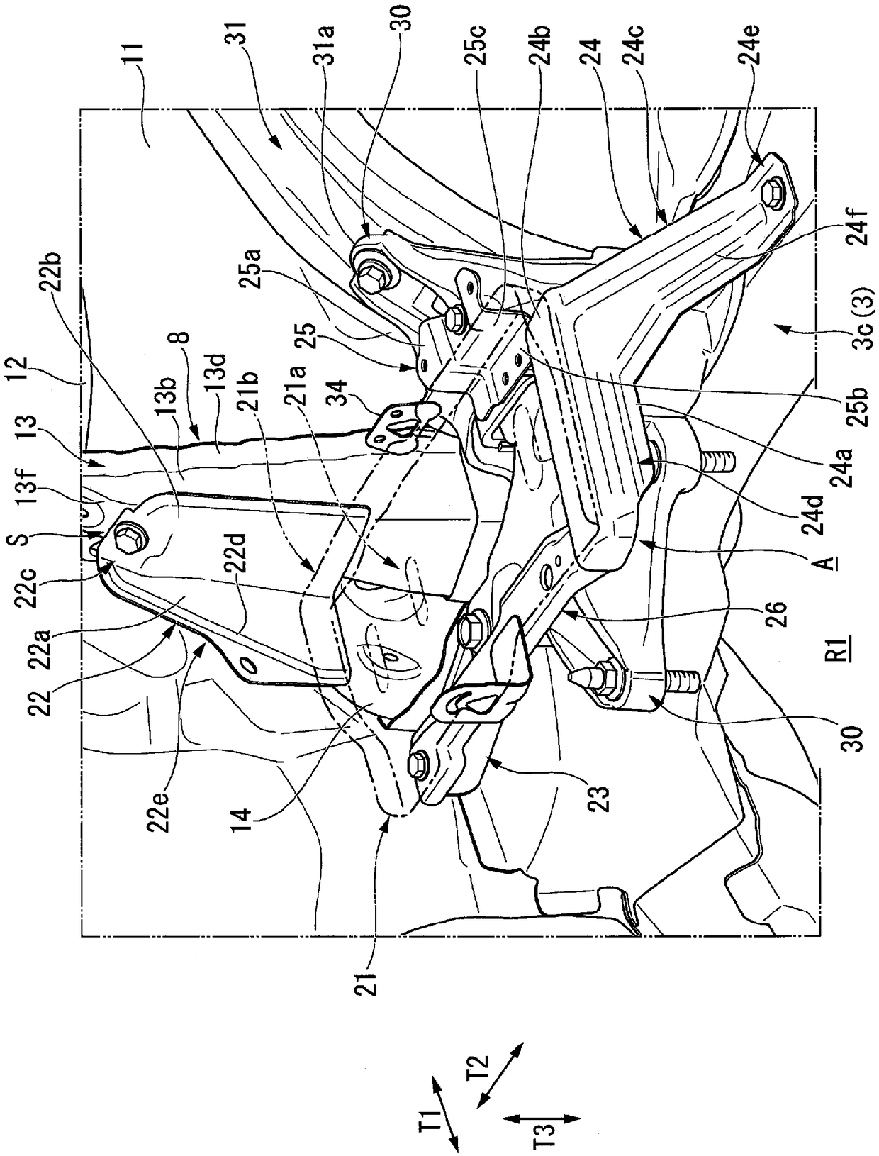
[0118] Below, refer to Figure 1 to Figure 9 A battery support structure according to one embodiment of the present invention will be described. Here, the present embodiment relates to a battery support structure provided in an engine compartment of a front structure of a vehicle to support a battery for supplying electric power to various electrical components.

[0119] First, if figure 1 As shown, the vehicle body 1 of this embodiment is divided into a vehicle compartment R2 and an engine compartment R1 by an instrument panel 2 arranged at its front portion, and consists of a front side frame 3, an outrigger 4, a front pillar 5, an upper The component 6, the shock absorber housing unit 7, the reinforcement unit 8, etc. form the skeleton of the front part.

[0120] The front side frames 3 extend in the front-rear direction T2 of the vehicle body 1 and are respectively disposed at lower portions of the engine room R1 on both sides in the vehicle width direction T1. The fro...


PUM


Abstract

The present invention provides a battery support structure that can stably support/hold a battery while achieving space saving and weight reduction. The battery supporting structure (A) is used for supporting a battery carried by a battery carrying portion (21), disposed on the front side frame (3) and at a side inside the vehicle width direction (T1) of a damper housing (11). The battery supporting structure is provided with a suspension supporting portion (22), as a first supporting component (22), for suspending and supporting the battery carrying portion (21). The suspension supporting portion (22) is configured in a manner that one wall portion (22a) and another wall portion (22b) extending in the axis direction along the vertical direction (T3) form a substantially L shape, the upperend is fixed to a position near a damper seat (12) at the upper end side of the damper housing (11), and the battery carrying portion (21) is fixed to the lower end, thus supporting the battery carrying portion (21).

Description

technical field [0001] The present invention relates to a battery support structure that supports a battery of a vehicle. Background technique [0002] A battery for supplying electric power to various electrical components is mounted in the engine room of the vehicle. In addition, a conventional battery is placed on a battery supporting portion (battery tray) supported by a battery bracket, and is clamped by a pressure plate disposed above the battery and a pair of fastening rods respectively connected to both ends of the pressure plate. be kept. [0003] On the other hand, Patent Document 1 discloses a battery support structure including, as a battery bracket, a first bracket welded to the shock absorber case, and a second bracket connected to the first bracket and the battery mounting portion. frame, and support the battery carrying part in a cantilevered state. [0004] However, in the battery support structure of Patent Document 1, when the vehicle is suddenly braked...

Claims


Application Information

Patent Timeline
Patent Type & Authority Applications(China)
IPC IPC(8): B60R16/04
CPCB60R16/04Y02E60/10
Inventor 松冈圣彦芳贺辉
Owner HONDA MOTOR CO LTD
Why Eureka
Try Eureka