
A kind of preloading device and construction method of high bridge pier with combined ballast at high altitude

A construction method and technology for bridge piers, which are applied to bridges, bridge construction, bridge parts, etc., can solve problems such as affecting the construction period, distributing a large number of beams, and large equipment requirements, avoiding the trouble of weighing, reducing engineering costs, and loading efficiency. high effect

Active Publication Date: 2021-01-15
SINOHYDRO BUREAU 8 CO LTD
View PDF5 Cites 0 Cited by
  • Summary
  • Abstract
  • Description
  • Claims
  • Application Information

AI Technical Summary

Problems solved by technology

Prefabricated concrete blocks, steel bars, water bags, bagged sand, etc. are commonly used as surcharge materials. However, if the bridge pier is high (up to 50m or more), the amount of solid concrete is large, and the surcharge operation area is narrow, conventional surcharges should be used to prefabricate the brackets. High pressure, high safety risk and high cost
At the same time, in the process of preloading and preloading, a large amount of preloaded materials (such as steel) need to be transferred, hoisted, and unloaded. The workload is heavy, the cost is high, the cycle is long, and the construction period is seriously affected.
The scheme design of the method of applying prestress is more complicated. If all prestress loading is used, a large number of distribution beams are required, and the installation of anchor bars is also troublesome. In addition, dozens of jacks are required, which requires a large amount of equipment and is difficult to implement on site. It is difficult to implement preloading of cast-in-place concrete brackets on high bridge piers with traditional loading methods

Method used


Image

  • A kind of preloading device and construction method of high bridge pier with combined ballast at high altitude
  • A kind of preloading device and construction method of high bridge pier with combined ballast at high altitude
  • A kind of preloading device and construction method of high bridge pier with combined ballast at high altitude

Examples


Embodiment Construction

[0033] The present invention will be further described in detail below in conjunction with the accompanying drawings and specific embodiments.

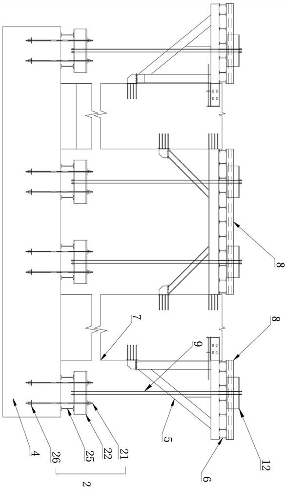
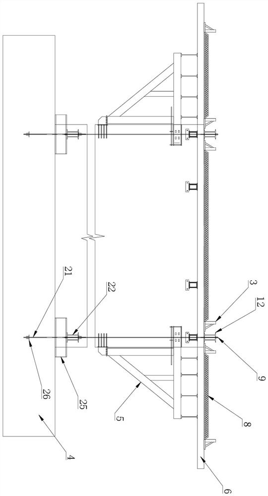
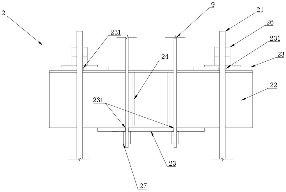
[0034] Such as Figures 1 to 5 As shown, a high-altitude combined ballast high pier preloading device of the present invention, the high pier preloading device is symmetrically arranged on both sides of the pier 7, including an upper anchor system 1, a lower anchor system 2, a bracket 5, and a steel strand The line system 9, the upper anchor system 1 is set on the distribution beam 6 above the bracket 5 and is perpendicular to the distribution beam 6, the lower anchor system 2 is located below the bracket 5 and connected with the platform 4, the upper anchor system 1 and the lower anchor system 2. Connected by the steel strand system 9, the high pier preloading device also includes load-bearing steel parts 8, which are located on both sides of the upper anchor system 1 and vertically arranged with the distribution beam 6, and the uppe...


PUM


Abstract

The invention discloses a high bridge pier preloading device with high-altitude combined pressure, adopting the combination of load-bearing steel parts and prestressed compressive load. An upper anchor system is arranged on the distribution beam above the bracket. A lower anchor system is arranged under that bracket. The upper anchor system and the lower anchor system are connected through a steelstrand system. The lower anchor system is connected to a bearing cap through connecting reinforcing bars. Load-bearing steel members are positioned on that distribution beam and distributed on both sides of the upper anchor system. Correspondingly, the invention also provides a construction method of the preloading device, comprising installing an upper anchor system and a lower anchor system, connecting the upper anchor system and the lower anchor system with a steel strand system, loading the load-bearing steel parts on a distribution beam in stages, observing and unloading the load-bearingsteel parts after loading is completed. The device and the method have the advantages of safety, convenience and simplicity.

Description

technical field [0001] The invention relates to the technical field of cast-in-situ concrete preloading devices for high bridge piers, in particular to a high bridge pier preloading device with high-altitude combined ballast and a construction method thereof. Background technique [0002] The conventional preloading of brackets is the preloading preloading and prestressing methods. Prefabricated concrete blocks, steel bars, water bags, bagged sand, etc. are commonly used as surcharge materials. However, if the bridge pier is high (up to 50m or more), the amount of solid concrete is large, and the surcharge operation area is narrow, conventional surcharges should be used to prefabricate the brackets. High pressure, high security risk and high cost. At the same time, in the process of preloading and preloading, a large amount of preloading materials (such as steel) need to be transferred, hoisted, and unloaded. The workload is heavy, the cost is high, and the cycle is long, w...

Claims


Application Information

Patent Timeline
Patent Type & Authority Patents(China)
IPC IPC(8): E01D21/00E01D19/02
CPCE01D19/02E01D21/00
Inventor 王伯俞黄巍李亚民刘昊夫李金恒朱向阳苏迎瑞江群德王东平杨嘉中石夜明
Owner SINOHYDRO BUREAU 8 CO LTD
Learn More