
Building detachable floor formwork

A detachable formwork technology, which is applied in the direction of construction, building structure, formwork/formwork components, etc., can solve the problems of low construction efficiency and damage to wood boards, and achieve the effect of improving service efficiency and service life

Inactive Publication Date: 2019-01-15
东莞市皓奇企业管理服务有限公司
View PDF0 Cites 0 Cited by
  • Summary
  • Abstract
  • Description
  • Claims
  • Application Information

AI Technical Summary

Problems solved by technology

[0002] At present, when people build a floor, they need to nail a floor cavity with wooden boards, and then pour concrete slurry into the cavity of the wooden board. After the concrete slurry is solidified, the wooden board is pried up, causing damage to the wooden board and low construction efficiency; Detachable floor formwork has become a need to reduce labor intensity and improve formwork efficiency and life

Method used


Image

  • Building detachable floor formwork
  • Building detachable floor formwork
  • Building detachable floor formwork

Examples


Embodiment Construction

[0012] Below in conjunction with accompanying drawing and specific embodiment the present invention is further described:

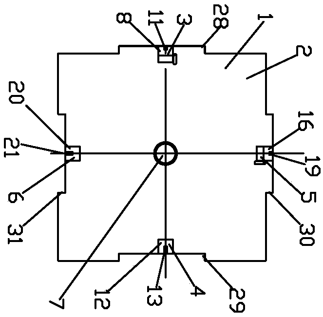
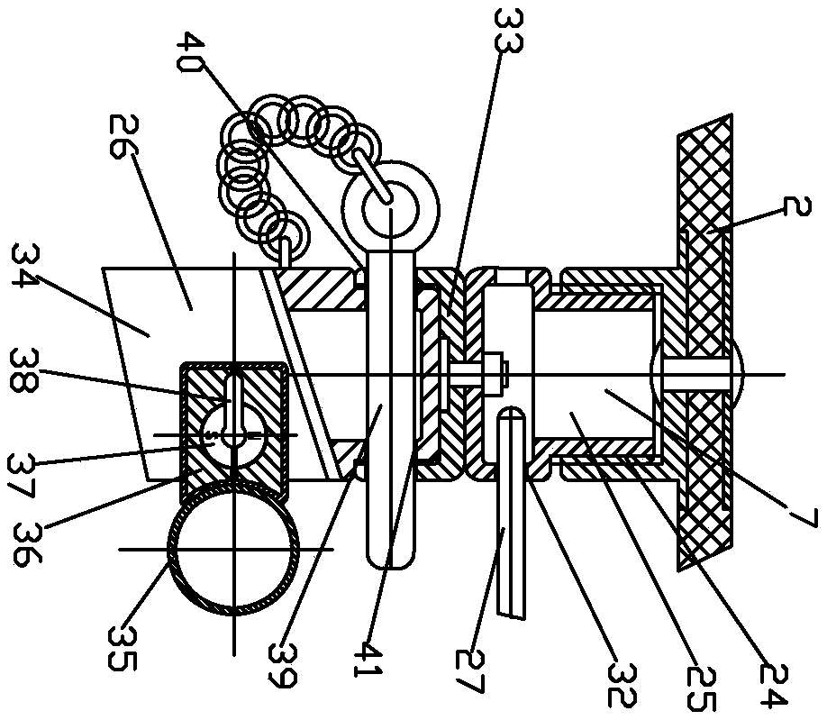
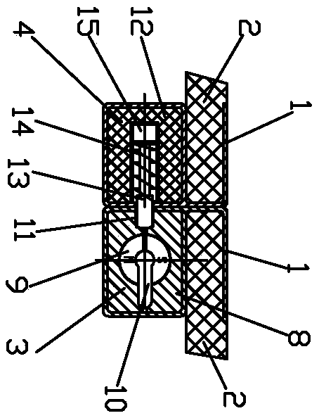
[0013] Such as figure 1 The structural schematic diagram of the detachable floor formwork shown in the building, figure 2 Shown is a schematic diagram of the structure of the adjustable support joint, image 3 Schematic diagram of the connection of the transverse magnetic base shown, Figure 4 The schematic diagram of the longitudinal magnetic base connection shown, Figure 5 The schematic diagram of the connection of the detachable floor formwork shown in the building; the detachable floor formwork of the building is composed of a plurality of magnetic formwork 1, and each magnetic formwork 1 includes a formwork 2, a horizontal magnetic base 3, a horizontal connection device 4, a vertical Magnetic base 5, vertical connecting device 6 and adjustable support joint 7, template 2 is fixedly connected with horizontal magnetic base 3, horizontal connecting...


PUM


Abstract

The invention discloses a building detachable floor formwork, which is composed of a plurality of magnetic formworks, wherein each magnetic formwork comprises a formwork, a transverse magnetic base, atransverse connecting device, a longitudinal magnetic base, a longitudinal connecting device and an adjustable supporting joint; and each formwork is provided with a left boss, a right notch, an upper boss and a lower notch. When in use, a bracket supporting the formworks is set up by means of connecting magnetic bases and connecting pipes, the formworks are connected with the bracket, then the left bosses and the right notches of the adjacent formworks are plugged, the upper bosses and the lower notches of the adjacent formworks are plugged, the adjacent formworks are connected by means of the transverse magnetic bases, the transverse connecting devices, the longitudinal magnetic bases and the longitudinal connecting devices, a pouring mold cavity of a floor is formed by means of the formworks, and a method of connection by means of iron nails is avoided. After the concrete floor is solidified and hardened, the longitudinal and transverse magnetic connection of the formworks is released, the formworks and the bracket are detached, the damage-free connection and detachment of the formwork are implemented, the usage efficiency of the formwork is improved, and the service life of the formwork is prolonged.

Description

technical field [0001] The invention relates to a building template, in particular to a building detachable floor template. Background technique [0002] At present, when people build a floor, they need to nail a floor cavity with wooden boards, and then pour concrete slurry into the cavity of the wooden board. After the concrete slurry is solidified, the wooden board is pried up, causing damage to the wooden board and low construction efficiency; Detachable floor formwork has become a need to reduce labor intensity and improve formwork efficiency and life. Contents of the invention [0003] The purpose of the present invention is to overcome the deficiencies of the prior art and provide a detachable building formwork for improving the use efficiency and lifespan of the formwork. [0004] The technical solution adopted by the present invention is: the detachable floor formwork of the building is composed of a plurality of magnetic formworks, and each magnetic formwork inc...

Claims


Application Information

Patent Timeline
IPC IPC(8): E04G11/36E04G9/08E04G17/00
CPCE04G11/36E04G9/08E04G17/00
Inventor 林智勇
Owner 东莞市皓奇企业管理服务有限公司
Learn More