
EGR Power Module and Method of Use Thereof

Active Publication Date: 2016-10-06
MCARDLE ENTERPRISES LLC
View PDF36 Cites 0 Cited by
  • Summary
  • Abstract
  • Description
  • Claims
  • Application Information

AI Technical Summary

Benefits of technology

This patent describes an exhaust gas recirculation (EGR) power module for controlling an engine's EGR system, which improves engine efficiency without needing to remove or modify the existing system. The module is designed to match the wire harness of the altimetric / barometric pressure sensor and / or ambient air sensor in the EGR system. The module includes a set of wires and a circuit that provides a resistance or a steady electrical current flow to the wire harness. The method of controlling the EGR system involves installing the EGR power module on the wire harness and controlling the system with it. The technical effects include improved engine efficiency and lifespan without the need for costly modifications or downtime.

Problems solved by technology

Because NOx forms primarily when a mixture of nitrogen and oxygen is subjected to high temperature, the lower combustion chamber temperatures caused by EGR may reduce the amount of NOx the combustion generates, which consequently causes some loss of engine efficiency.
However, EGRs appear to be a very expensive technology over the long haul for reducing NOx emissions.
For example, at idle when there is otherwise a large excess of air in controlling NOx emissions, it has been discovered that exhaust recirculated back into the cylinder can increase engine wear as carbon particulate wash past the rings and into the oil.
However, it has been discovered that adding EGR to a diesel reduces the specific heat ratio of the combustion gases in the stroke of the engine, i.e. the power stroke.
This reduces the amount of power that can be extracted by the piston.
Particulate matter (mainly carbon) that is not burned in the power stroke is wasted energy.
The most common is a diesel particulate filter in the exhaust system which cleans the exhaust but reduces fuel efficiency.
This makes combustion less efficient, compromising economy and power.
The normally “dry” intake system of a diesel engine is now subject to fouling from soot.
Unburned fuel and oil in the EGR bleed, which has little effect on airflow, when combined with oil vapor from a Crankcase ventilation system (PCV system), can cause buildup of sticky tar in the intake manifold and valves.
It has also been discovered to cause problems with components such as swirl flaps, where fitted.
EGR systems have also been discovered to add abrasive contaminants and increase engine oil acidity, which in turn can reduce engine longevity.
Poor EGR performance occurs often, with hesitation, smoking, coughing, backfiring, and poor fuel mileage.
Currently, devices only remove the EGR system, which is illegal unless used in an off road situation.
In sum, it has been discovered that EGR can be a disadvantage to engine efficiency through: 1) shortened engine lubricant life; 2) increased carbon / soot deposits throughout the engine; 3) reduced engine performance; 4) reduced fuel economy; 5) increased emissions; 6) both minor and catastrophic power train component / engine failure / reduced engine / equipment life; 7) damaged emission controls IE, EGR, turbo, diesel particulate filter; 8) cost of time, expense and inconvenience to the operator / end user; the like; and / or combinations thereof.
Depending on the use of the vehicle, it has been discovered that these problems can crop up in a very short time and even in ideal conditions they may still develop.
It is quite evident that, prior to the instant disclosure, researchers may be still trying to identify cause and effect of the EGR system and clearly have no solution to the problem.

Method used


Image

  • EGR Power Module and Method of Use Thereof
  • EGR Power Module and Method of Use Thereof
  • EGR Power Module and Method of Use Thereof

Examples


examples

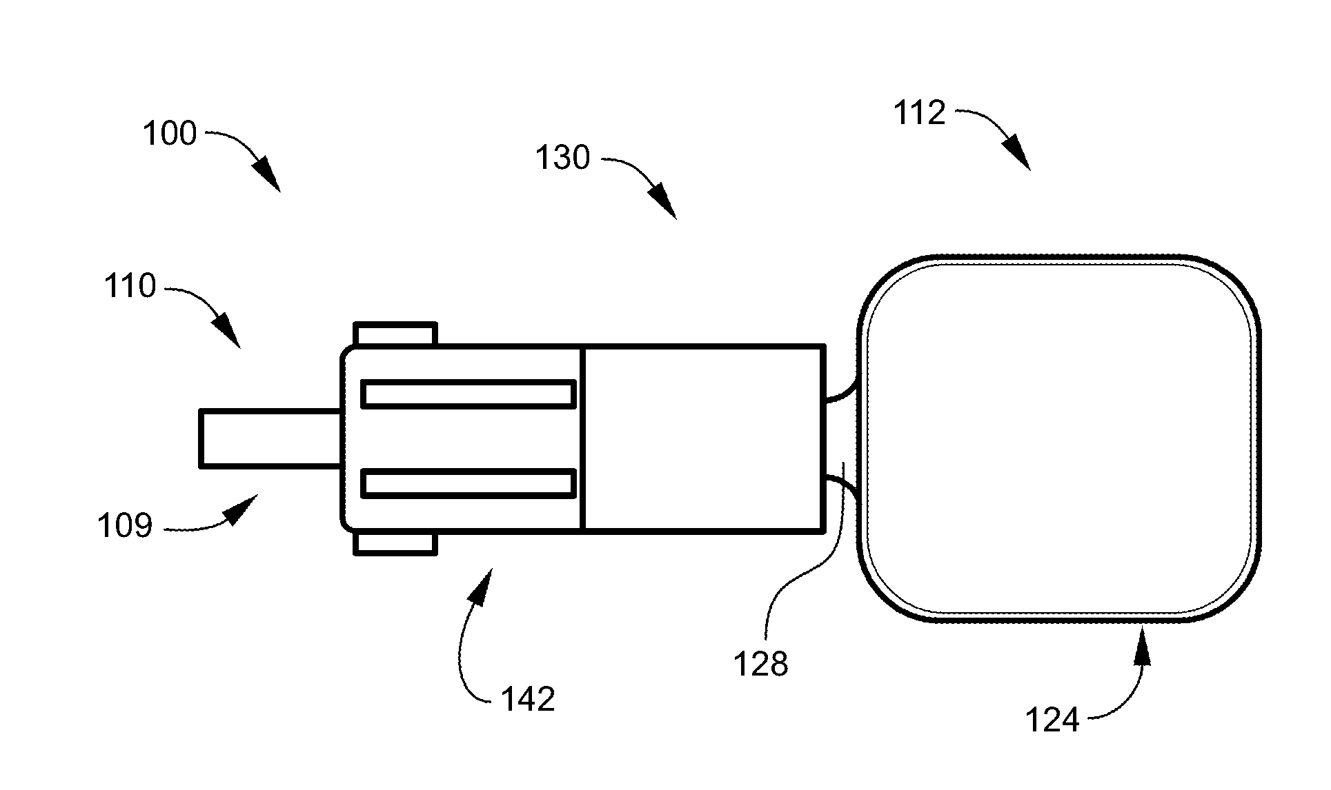
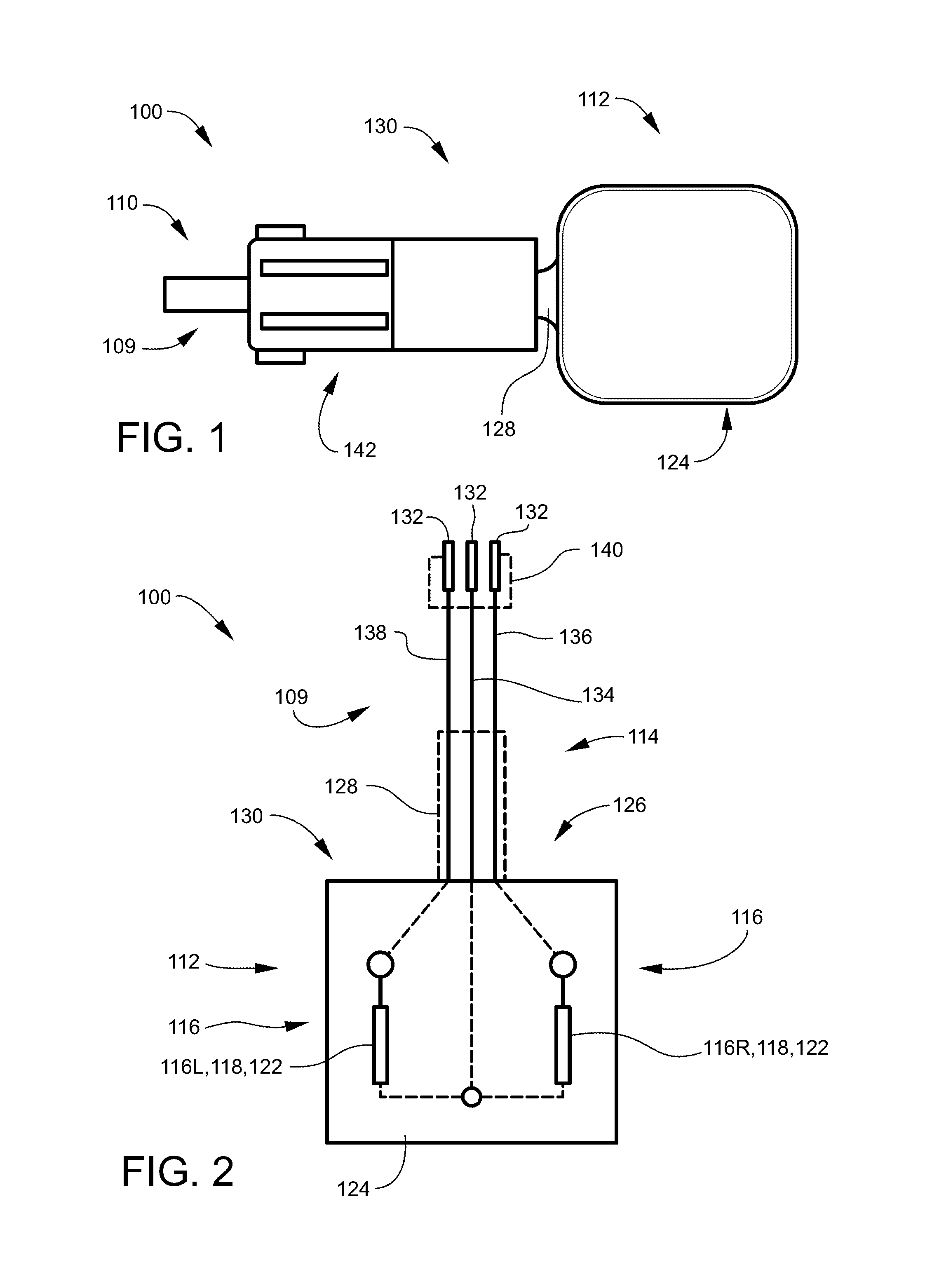
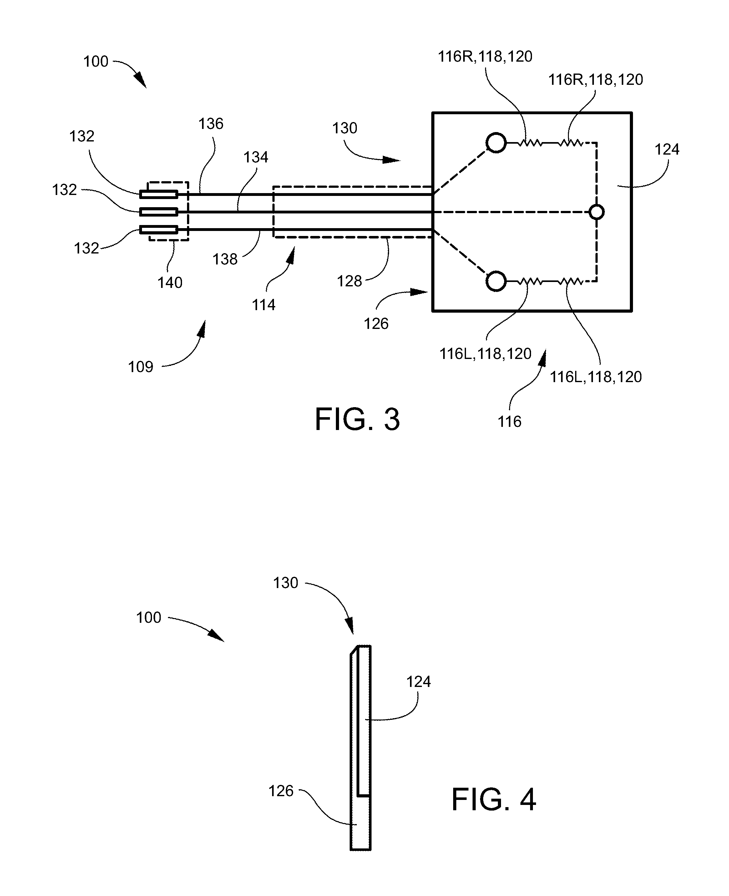
[0086]Referring to FIGS. 1-3, an embodiment of the present disclosure of EGR power module 100 was created with perforated pc board 124 covered in epoxy 126. A plurality of resistors 118 were attached to pc board 124. Set of wires 109 were connected to the center of the plurality of resistors and to the end of each resistor. Heat shrink tubing 128 covers set of wires 109. All components were dipped in multipurpose rubber coating 130.

[0087]Input first wire 134, which may be red, was soldered to the center / bottom of the plurality of resistors 118, as shown as left and right electronic components 116L and 116R First output wire 136, which may be black, was soldered to the end of first resistor 118, as shown as right electronic component 116R. Second output wire 138, which may be white, green or the like, may be soldered to the second resistor 118, as shown as left electronic component 116L. Heat shrink tubing 128 was attached to the outside of input wire 134, first output wire 136, and ...


PUM


Abstract

An exhaust gas recirculation (“EGR”) power module configured for a wire harness of an altimetric / barometric pressure sensor and / or an ambient air sensor of an EGR system for an engine includes a set of wires and a circuit. The set of wires is configured to match the wire harness on the altimetric / barometric pressure sensor and / or the ambient air sensor for the engine. The circuit provides a resistance or resistances to the wire harness through the set of wires.

Description

CROSS-REFERENCE TO RELATED APPLICATIONS[0001]This application claims benefit to U.S. Non-Provisional patent application Ser. No. 14 / 662,778, filed on Mar. 19, 2015, which claims benefit to U.S. Provisional Patent Application No. 61 / 955,359, filed on Mar. 19, 2014, which is incorporated by reference in its entirety.FEDERALLY SPONSORED RESEARCH OR DEVELOPMENT[0002]NonePARTIES TO A JOINT RESEARCH AGREEMENT[0003]NoneREFERENCE TO A SEQUENCE LISTING[0004]NoneBACKGROUND OF THE DISCLOSURE[0005]1. Technical Field of the Disclosure[0006]The disclosure generally relates to internal combustion engines and exhaust gas recirculation (“EGR”) systems of such internal combustion engines. More specifically, the disclosure relates to an EGR power module for controlling the EGR systems of internal combustion engines and methods of use thereof.[0007]2. Description of the Related Art[0008]In internal combustion engines, exhaust gas recirculation (“EGR”) is a process where nitrogen oxide (NOx) emissions i...

Claims


Application Information

Patent Timeline
IPC IPC(8): F02D41/00B60R16/03B60R16/02F02M26/11F02M26/47
CPCF02D41/0072F02M26/11B60R16/03B60R16/0207F02M26/47F02D41/0065F02D2400/11
Inventor HANAK, ANTHONY STEPHEN
Owner MCARDLE ENTERPRISES LLC
Learn More