Transposition tower and transposition method
A transposition tower and wire transposition technology, which is applied in the space arrangement/configuration of towers and cables, building types, etc., can solve problems such as inconvenient operation and maintenance, many jumpers, and complex structures
- Summary
- Abstract
- Description
- Claims
- Application Information
AI Technical Summary
Problems solved by technology
Method used
Image
Examples
Embodiment 1
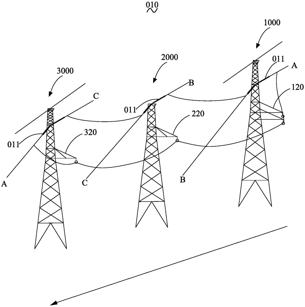
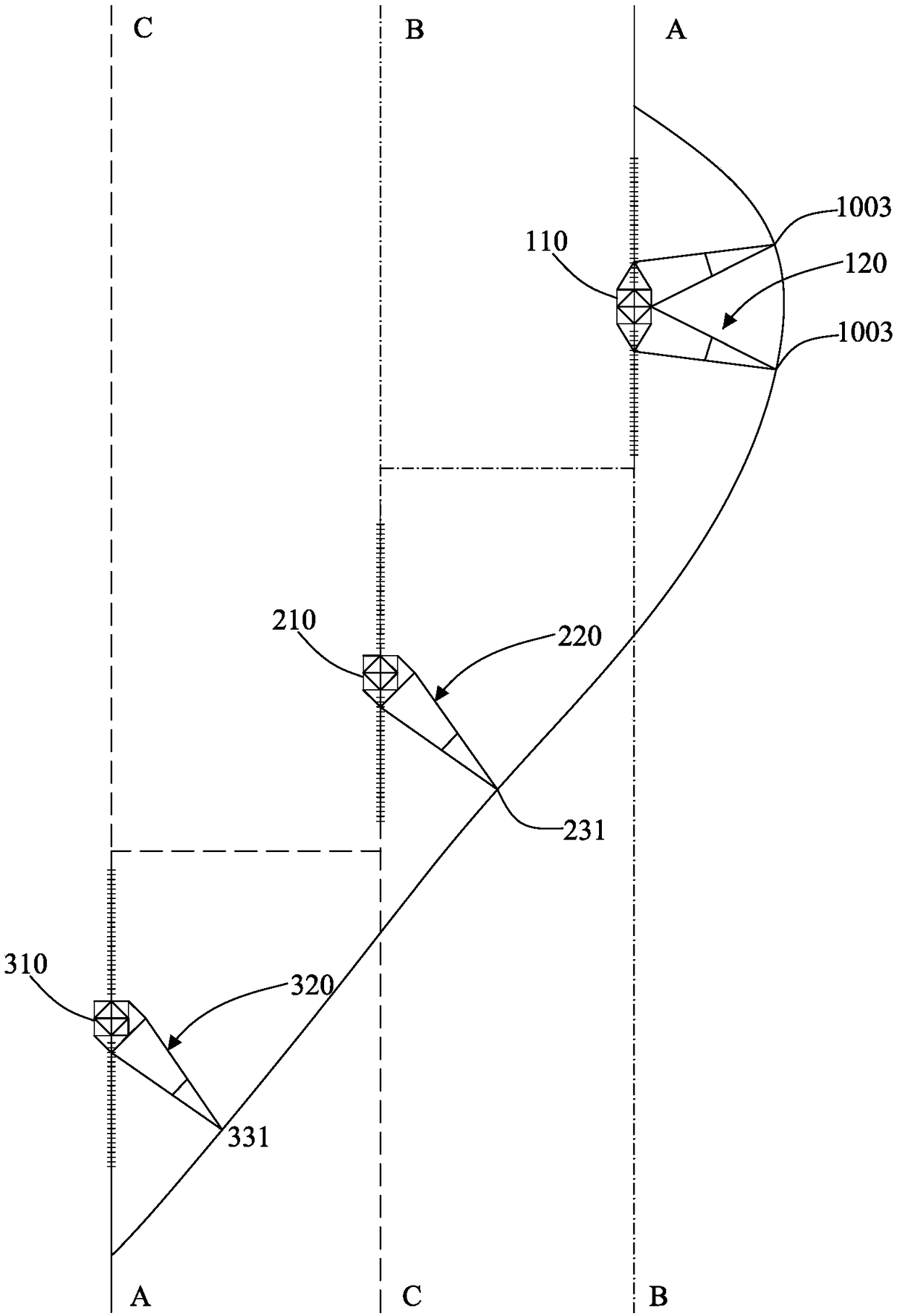
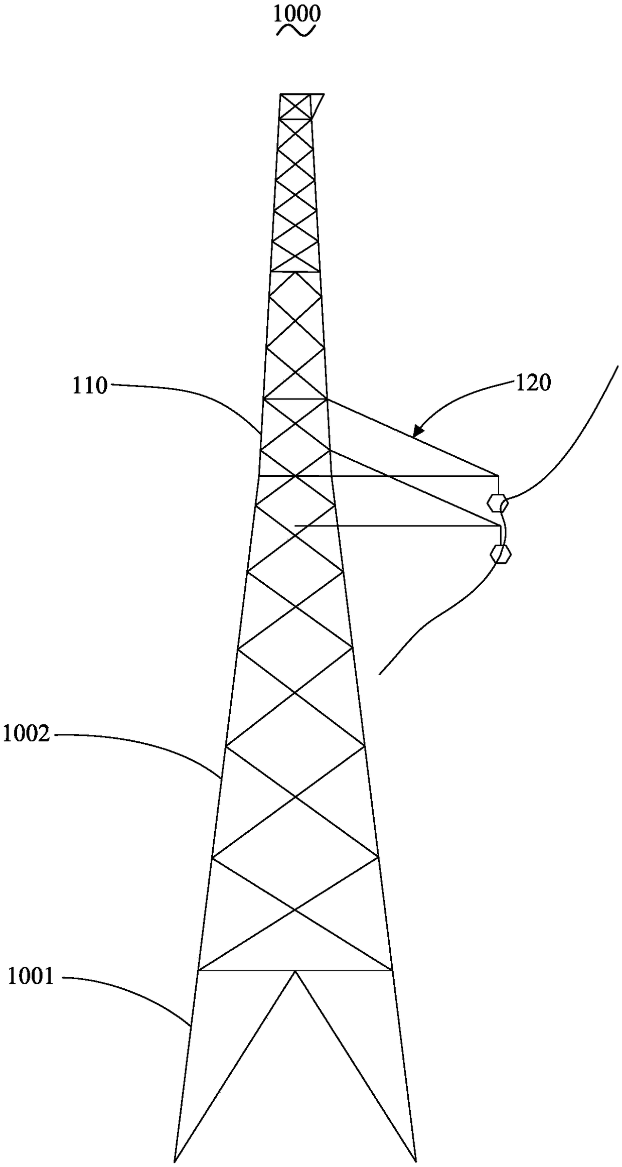
[0043] Such as figure 1 with figure 2 As shown, the transposition tower 010 of Embodiment 1 of the present invention is used to transpose the three-phase conductors. The transposition tower 010 includes a first main tower 1000, a second main tower 2000, and a third main tower 3000. The three-phase conductors are respectively denoted Phase A, Phase B, and Phase C. The first main tower 1000, the second main tower 2000, and the third main tower 3000 are arranged in sequence along the direction of the transmission line. The first main tower 1000, the second main tower 2000, and the third main tower The 3000 is arranged in a dislocation along the vertical direction of the transmission line, the A-phase conductor is mounted on the first main tower 1000, the second main tower 2000, and the third main tower 3000 in sequence, and the B-phase conductor is mounted on the second main tower 2000, On the first main tower 1000 , the C-phase conductors are mounted on the third main tower 30...
Embodiment 2
[0090] see Figure 13 , the structure of the double-pointed cross-arm 420 in this embodiment is basically the same as that of the double-pointed cross-arm 120 in Embodiment 1, the difference is that in each group of pointed cross-arms 430, the first cross-arm insulator 440 and the second The cross-arm insulator 450 is composed of a composite insulator, and no auxiliary cross-arm insulator is provided. The second cross-arm insulator 450 of one group of pointed cross-arms 430 is directly connected to the midpoint of the second angle steel 402 through a connecting piece, so as to be connected to the tower head 410 without auxiliary arms and auxiliary cable-stayed insulators. The structure of another set of pointed cross arms 430 is the same as that of the pointed cross arms 130 in the first embodiment.
[0091] Of course, the present invention is not limited thereto. In other embodiments, the second cross-arm insulators 450 in the two sets of pointed cross-arms 430 may also be d...
Embodiment 3
[0094] see Figure 14 , the structure of the double-pointed cross-arm 520 in this embodiment is basically the same as that of the double-pointed cross-arm 120 in Embodiment 1, the difference is that each group of pointed cross-arms 530 is also provided with a third cable-stayed insulator 590 and A fourth cable-stayed insulator 591, one end of the third cable-stayed insulator 590 is connected to the connection between the first cable-stayed insulator 580 and the tower head 510, and the other end of the third cable-stayed insulator 590 is connected to the second cross-arm insulator 550 and The junction of the auxiliary cross-arm insulator 570. One end of the fourth cable-stayed insulator 591 is connected to the connection between the first cable-stayed insulator 580 and the tower head 510, and the other end of the fourth cable-stayed insulator 591 is connected to the connection between the first cross-arm insulator 540 and the auxiliary cross-arm insulator 570 .
PUM
 Abstract
Description
Claims
Application Information
 - R&D
- Intellectual Property
- Life Sciences
- Materials
- Tech Scout
- Unparalleled Data Quality
- Higher Quality Content
- 60% Fewer Hallucinations
Browse by: Latest US Patents, China's latest patents, Technical Efficacy Thesaurus, Application Domain, Technology Topic, Popular Technical Reports.
© 2025 PatSnap. All rights reserved.Legal|Privacy policy|Modern Slavery Act Transparency Statement|Sitemap|About US| Contact US: help@patsnap.com


