Double-apex cross arm and power transmission tower
A technology of transmission towers and crossarms, applied in the field of transmission insulation equipment, can solve problems such as complex structure, waste, and increased cost
- Summary
- Abstract
- Description
- Claims
- Application Information
AI Technical Summary
Problems solved by technology
Method used
Image
Examples
Embodiment 1
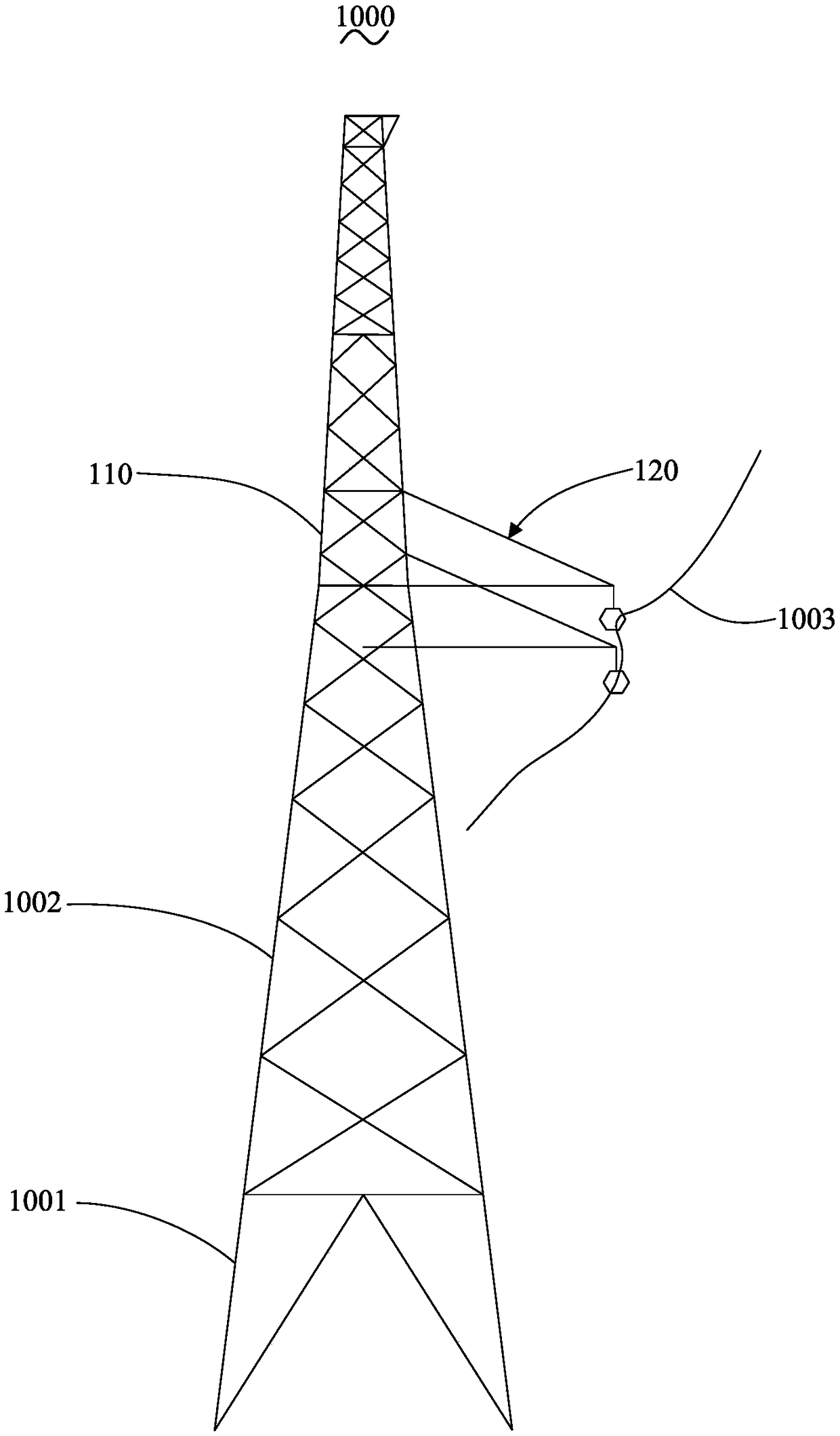
[0027] like figure 1 As shown, the transmission tower 1000 of this embodiment is a lattice steel tower, which has a tower leg 1001, a tower body 1002 connected above the tower leg 1001, and a tower head 110 connected above the tower body 1002, and the tower head 110 is provided with There are double-pointed cross-arms 120, and the double-pointed cross-arms 120 are used to hang the wires 1003, and the section of the tower head 110 along the horizontal plane is a square. The tower legs 1001, the tower body 1002 and the tower head 110 are all made of angle steel.
[0028] Of course, the present invention is not limited thereto. In other embodiments, the power transmission tower 1000 may also use other metal materials such as iron, or may also use composite materials. The section of the tower head 110 along the horizontal plane may also be rectangular.
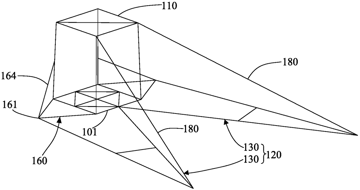
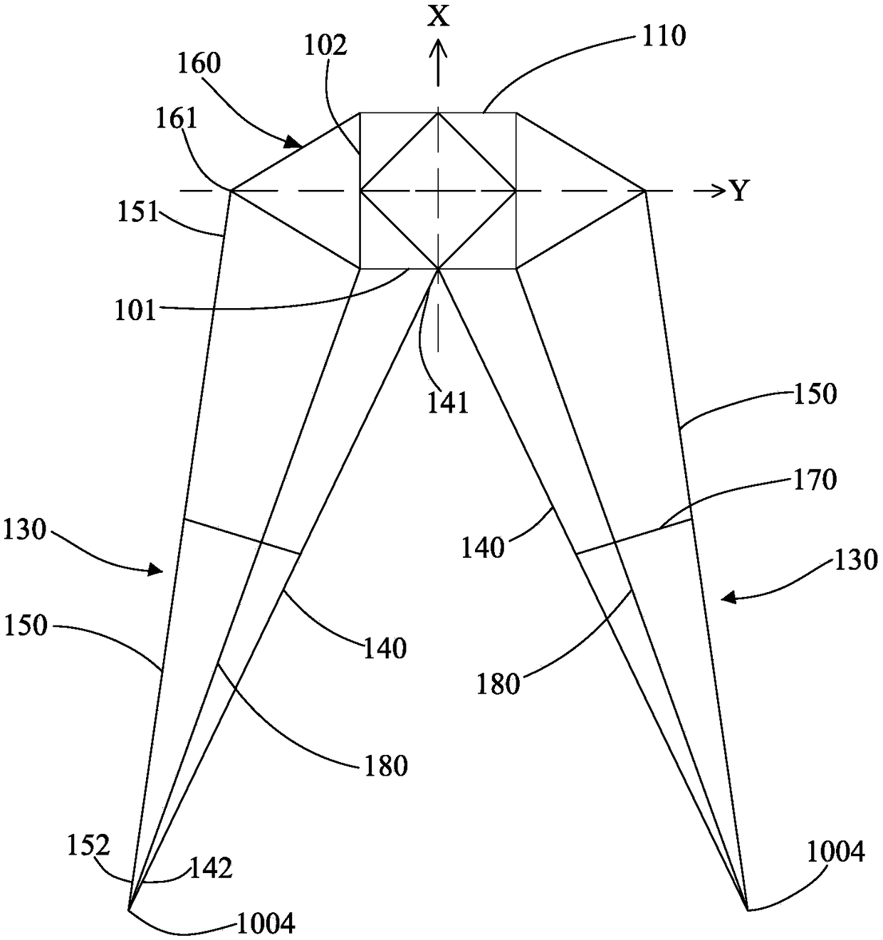
[0029] like figure 2 , image 3 As shown, in this embodiment, the double-pointed cross-arm 120 has two sets of pointed cros...
Embodiment 2
[0047] see Figure 7 , the structure of the double-pointed cross-arm 220 in this embodiment is basically the same as that of the double-pointed cross-arm 120 in Embodiment 1, the difference is that in each group of pointed cross-arms 230, the first cross-arm insulator 240 and the second The cross-arm insulators 250 are all composed of a composite insulator, and no auxiliary cross-arm insulators are provided. The second cross-arm insulator 250 of one set of pointed cross-arms 230 is directly connected to the midpoint of the second angle steel 202 through a connecting piece, thereby connecting to the tower head 210, without auxiliary arms and auxiliary cable-stayed insulators. The structure of another group of pointed cross arms 230 is the same as that of the pointed cross arms 130 in the first embodiment.
[0048] Of course, the present invention is not limited thereto. In other embodiments, the second cross-arm insulators 250 in the two sets of pointed cross-arms 230 may also...
Embodiment 3
[0050] see Figure 8The structure of the double-pointed cross-arm 320 in this embodiment is basically the same as that of the double-pointed cross-arm 120 in Embodiment 1, the difference is that each group of pointed cross-arms 330 is also provided with a second cable-stayed insulator 390 and A third cable-stayed insulator 391, one end of the second cable-stayed insulator 390 is connected to the connection between the first cable-stayed insulator 380 and the tower head 310, and the other end of the second cable-stayed insulator 390 is connected to the second cross-arm insulator 350 and The junction of the auxiliary cross-arm insulator 370. One end of the third cable-stayed insulator 391 is connected to the connection between the first cable-stayed insulator 380 and the tower head 310, and the other end of the third cable-stayed insulator 391 is connected to the connection between the first cross-arm insulator 340 and the auxiliary cross-arm insulator 370 .
PUM
 Abstract
Description
Claims
Application Information
 - R&D
- Intellectual Property
- Life Sciences
- Materials
- Tech Scout
- Unparalleled Data Quality
- Higher Quality Content
- 60% Fewer Hallucinations
Browse by: Latest US Patents, China's latest patents, Technical Efficacy Thesaurus, Application Domain, Technology Topic, Popular Technical Reports.
© 2025 PatSnap. All rights reserved.Legal|Privacy policy|Modern Slavery Act Transparency Statement|Sitemap|About US| Contact US: help@patsnap.com


