Hoisting structure and hoisting method of fan coil
A fan coil unit and hoisting method technology, which is applied to heating methods, space heating and ventilation details, household heating, etc., can solve problems such as inconvenient installation, large errors, and inability to reflect data, so as to avoid the problem that the accuracy cannot be guaranteed Effect
- Summary
- Abstract
- Description
- Claims
- Application Information
AI Technical Summary
Problems solved by technology
Method used
Image
Examples
Embodiment 1
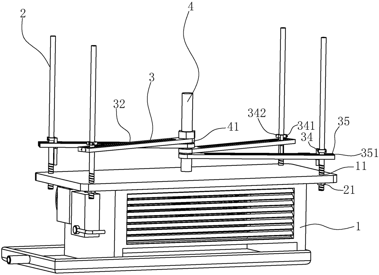
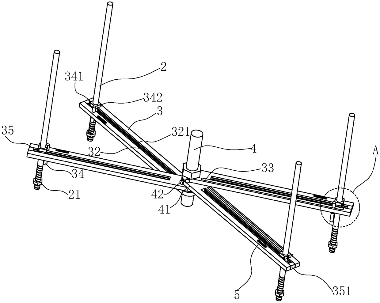
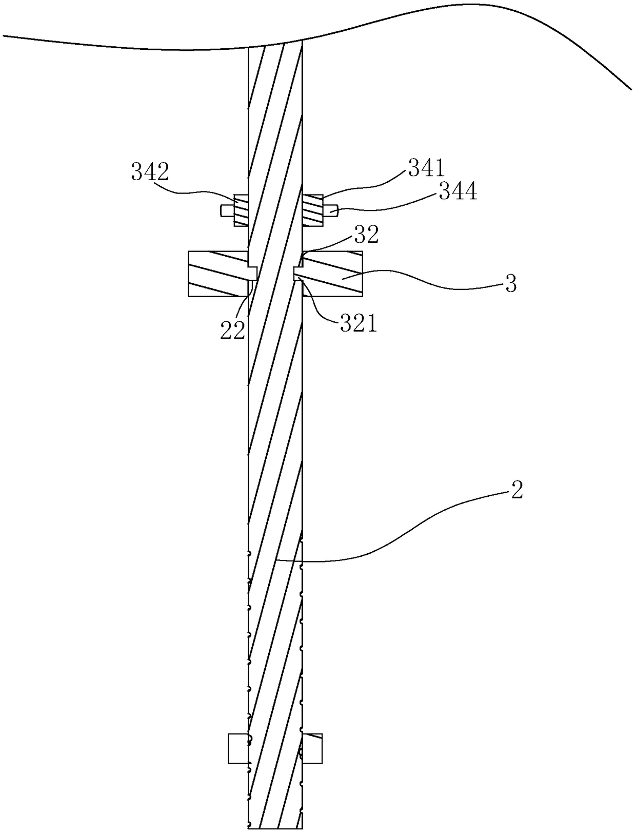
[0043] A hoisting structure for fan coil units, such as figure 1 As shown, it includes suspenders 2 located at the four peripheral corners of the fan coil unit 1. Here, the fan coil unit 1 is provided with fixing holes 11 corresponding to the suspenders 2. The suspenders 2 are vertically arranged, and the suspenders 2 The lower end that passes through the fixing hole 11 and passes through one side is provided with a positioning nut 21 that abuts against the side of the fan coil unit 1; in this embodiment, as figure 2 As shown, the boom 2 is provided with positioning rods 3 which are arranged corresponding to each other and are arranged horizontally. Positioning device, in the present embodiment, one of the ends of the four positioning rods 3 is concentrated at one point, and the positioning rods 3 are rotated and set along the centrally arranged point, and the positioning rods 3 are rotated to form a plane parallel to the horizontal plane; here, as figure 2 As shown, each p...
Embodiment 2
[0049] A hoisting method for a fan coil unit, which is based on the hoisting structure of a fan coil unit 1 in Embodiment 1 to realize the hoisting of the fan coil unit, such as figure 1 shown, including the following steps:
[0050] S1: Firstly, holes are drilled at the four peripheral corners of the fan coil unit 1 to form fixing holes 11 .
[0051] S2: slidingly install the suspender 2 on the positioning rod 3, and close the opening 35 on the positioning rod 3 through the cover plate 351.
[0052] In this way, the sliding installation of the suspension rod 2 is facilitated by the opening 35 on the positioning rod 3 , and the opening 35 is blocked by the setting of the cover plate 351 to prevent the suspension rod 2 from sliding out of the opening 35 along the positioning groove 32 .
[0053] S3: Rotate the positioning rod 3 along the axis of the fixed shaft 4, and slide the suspender 2 in the positioning groove 32 so that the suspender 2 corresponds to the fixing hole 11 o...
PUM
 Abstract
Description
Claims
Application Information
 - R&D
- Intellectual Property
- Life Sciences
- Materials
- Tech Scout
- Unparalleled Data Quality
- Higher Quality Content
- 60% Fewer Hallucinations
Browse by: Latest US Patents, China's latest patents, Technical Efficacy Thesaurus, Application Domain, Technology Topic, Popular Technical Reports.
© 2025 PatSnap. All rights reserved.Legal|Privacy policy|Modern Slavery Act Transparency Statement|Sitemap|About US| Contact US: help@patsnap.com


