
A method for calibrating the optical axis lead-out mechanism of a star sensor

A technology of star sensor, calibration method, applied in the direction of instruments, measuring devices, etc.

Active Publication Date: 2020-11-10
BEIJING INST OF CONTROL ENG
View PDF7 Cites 0 Cited by
  • Summary
  • Abstract
  • Description
  • Claims
  • Application Information

AI Technical Summary

Problems solved by technology

According to different displacement ranges, the single-axis deflection of the two-dimensional translation platform is generally several seconds to tens of seconds. At present, there is no relevant national regulation on the calibration method of the deflection error when the two axes of the translation platform are linked.

Method used


Image

  • A method for calibrating the optical axis lead-out mechanism of a star sensor
  • A method for calibrating the optical axis lead-out mechanism of a star sensor
  • A method for calibrating the optical axis lead-out mechanism of a star sensor

Examples


Embodiment Construction

[0058] Below in conjunction with accompanying drawing and specific embodiment the present invention is described in further detail:

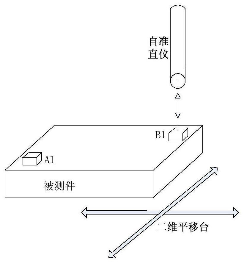
[0059] (1) Calibrate the error of the autocollimator by using an optical angle gauge and a plane mirror with a diameter of Φ80mm, and obtain the collimation measurement error of the autocollimator. The optical angle gauge, the autocollimator, and the facet mirror are placed on the same platform, the optical angle gauge is in the middle, and the main section of the optical angle gauge and the plane mirror are perpendicular to the visual axis of the autocollimator. Place the laser aligner on the autocollimator, adjust the yaw and pitch knobs on the base of the autocollimator, so that the laser alignment beam of the autocollimator hits the center of the optical square gauge and the outgoing beam and reflection The beams overlap as much as possible; take away the laser aligner, open the autocollimator measurement software, and observe the cross imag...


PUM


Abstract

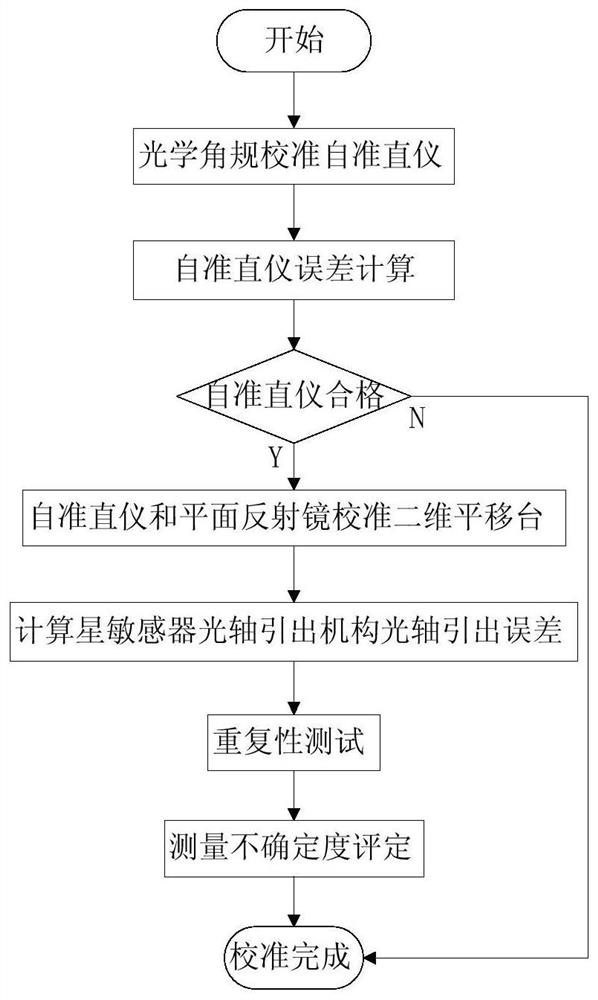
The invention discloses a method for calibrating an optical axis leading-out mechanism of a star sensor. The method comprises the steps of first conducting calibration on a collimation error of an autocollimator by using an optical angle gauge and a small-plane reflector; then, performing pointing deflection calibration of a two-dimensional translation platform by using the autocollimator and a large-plane reflector; and at last, evaluating the measurement uncertainty of a calibration result of the optical axis leading-out mechanism of the star sensor. According to the method provided by the invention, the pointing deflection calibration of the two-dimensional translation platform in the mechanism and the calibration test of the autocollimator in the site are solved, the calibration of anangle error of the optical axis leading-out mechanism of the star sensor is implemented, and the optical axis leading-out precision of the star sensor is improved.

Description

technical field [0001] The invention belongs to the field of measurement of special test equipment, and relates to a method for calibrating an optical axis lead-out mechanism of a star sensor. Background technique [0002] There are many factors that determine the accuracy level of the star sensor, among which the space adjustment accuracy between the key imaging components inside the star sensor is an important part of the hardware error factor. The pointing of the optical reference of the old star sensor is determined by the machining accuracy of its mounting surface relative to the lens mounting surface, which cannot truly reflect the pointing of the optical axis, with low precision and poor product consistency. In order to realize the extraction of the optical axis of the high-precision star sensor and improve the accuracy of key benchmark precision assembly and adjustment, a set of optical axis extraction mechanism of the star sensor is developed. Leading out the line,...

Claims


Application Information

Patent Timeline
Patent Type & Authority Patents(China)
IPC IPC(8): G01C25/00
CPCG01C25/00
Inventor 张瀚文王晓燕于志军马德智
Owner BEIJING INST OF CONTROL ENG
Learn More