Dynamic and cyclic direct shear test method for rock mass structural planes

A test method and dynamic cycle technology are applied in the direction of testing material strength by applying stable shear force, testing material strength by applying repetitive force/pulsation force, and measuring devices, which can solve the lack of understanding of dynamic cycle shear characteristics, Lack of other issues

Active Publication Date: 2019-01-15
INST OF GEOLOGY & GEOPHYSICS CHINESE ACAD OF SCI
View PDF7 Cites 9 Cited by
  • Summary
  • Abstract
  • Description
  • Claims
  • Application Information

AI Technical Summary

Problems solved by technology

Due to the lack of a complete set of test methods for testing the dynamic shear characteristics of rock mass discontinuities, the predecessor

Method used


Image

  • Dynamic and cyclic direct shear test method for rock mass structural planes
  • Dynamic and cyclic direct shear test method for rock mass structural planes
  • Dynamic and cyclic direct shear test method for rock mass structural planes

Examples


Embodiment 1

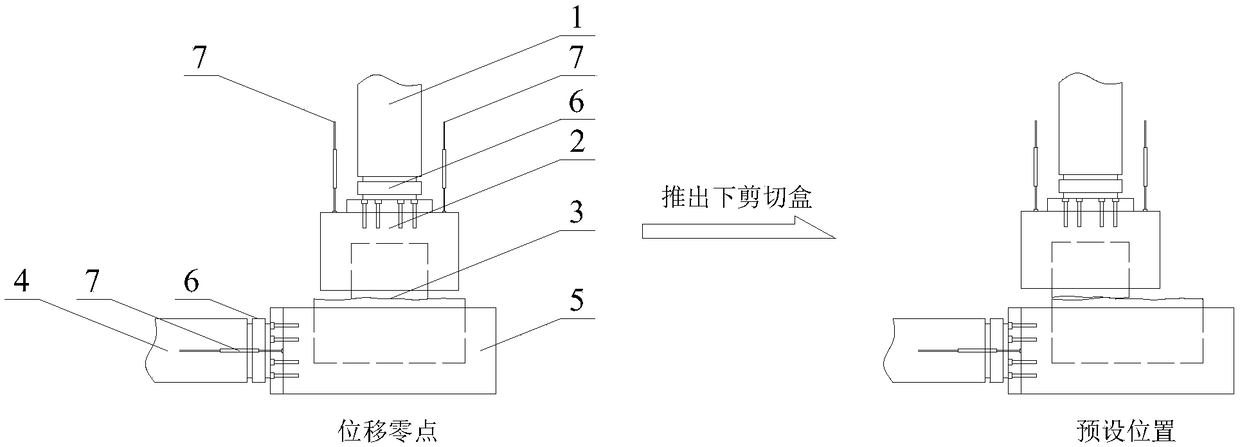
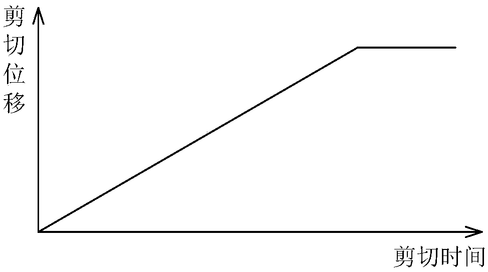
[0036] Please refer to figure 1 and figure 2 , The steps of the uniform velocity unidirectional direct shear test method for the rock mass structure surface are: first, the normal load is applied to the rock mass structure surface 3 by controlling the normal oil cylinder 1 and the upper shear box 2; The lower shear box 5 is pushed out to the oil cylinder 4 at a constant speed and then acts on the rock mass structure surface 3. The rock mass structure surface 3 is the contact between the upper shear box 2 and the rock blocks in the lower shear box 5. The length of the rock blocks in the upper shear box 2 along the shear direction is smaller than that in the lower shear box 5, and the moving speed of the lower shear box 5 is determined according to the dynamic test requirements, and the rate range can be selected from 0.001 to 1000mm / s; during the test, the test data is recorded by the force sensor 6 and the displacement sensor 7; finally, the test is stopped when the lower sh...

Embodiment 2

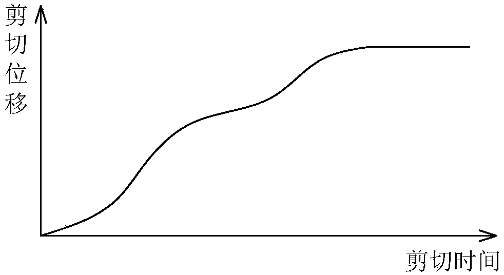
[0038] Please refer to figure 1 and image 3 , The steps of the variable-speed unidirectional direct shear test method for the rock mass structure surface are: first, the normal load is applied to the rock mass structure surface 3 by controlling the normal oil cylinder 1 and the upper shear box 2; The lower shear box 5 is pushed out to the oil cylinder 4 at a constant shear direction and at a changing rate, and then acts on the rock mass structure surface 3. The movement rate of the lower shear box 5 is determined according to the dynamic test requirements; during the test, the force The sensor 6 and the displacement sensor 7 record the test data; finally, the test is stopped when the lower shear box 5 moves to the preset position, and the distance between the preset position and the displacement zero point is between 0 and the rock blocks in the lower and upper shear boxes. Between the length differences and the rock blocks in the upper shear box are never separated from the...

Embodiment 3

[0040] Please refer to Figure 4 and Figure 5, The steps of the one-way cyclic direct shear test method for the rock mass structure surface are: first, the normal load is applied to the rock mass structure surface 3 through the control normal oil cylinder 1 and the upper shear box 2; The lower shear box 5 is pushed out to the oil cylinder 4 at a constant shearing direction and a certain speed, and then acts on the rock mass structure surface 3. When the lower shear box 5 moves to the preset position, the tangential oil cylinder 4 is pushed out by controlling the tangential oil cylinder 4. Then pull back the lower shear box 5, the distance between the preset position and the displacement zero point is between the 0 value and the difference between the lengths of the rock blocks in the lower and upper shear boxes, and the rock blocks in the upper shear box are always Do not detach from the rock block surface in the lower shear box; when the lower shear box 5 moves to the displ...


PUM


Abstract

The invention discloses a dynamic and cyclic direct shear test method for rock mass structural planes, comprising a dynamic direct shear test method for rock mass structural planes and a cyclic directshear test method for rock mass structural planes. The dynamic direct shear test method for rock mass structural planes comprises a uniform speed on-way direct shear test method for rock mass structural planes and a variable speed one-way direct shear test method for rock mass structural planes. The cyclic direct shear test method for rock mass structural planes comprises a cyclic one-way directshear test method for rock mass structural planes, a two-way cyclic direct shear test method for rock mass structural planes, and a loading/unloading direct shear test method for rock mass structuralplanes. The dynamic and cyclic direct shear test method for rock mass structural planes can be applied to the dynamic direct shear test system of rock mass structural planes to test the dynamic and cyclic shear characteristics of the structural planes, so as to achieve different research purposes.

Description

technical field [0001] The invention relates to the field of rock mass mechanics experiments, in particular to a dynamic cyclic direct shear test method for a rock mass structural plane. Background technique [0002] The stability of engineering rock mass under the action of ground motion is one of the focus issues of the engineering and scientific circles. Accurately grasping the mechanical properties of the rock mass structural plane is the key to the evaluation of engineering rock mass stability. The seismic load is both a dynamic load and a cyclic load. For a sloped slope that is stable under static conditions, under the dynamic cyclic shearing action of the seismic load, the strength of the structural surface changes, resulting in the dislocation or slippage of the slope along the structural surface. , resulting in collapses, landslides and other disasters. Therefore, the deformation and strength characteristics of rock mass structural plane under the action of seismic...

Claims


Application Information

Patent Timeline
IPC IPC(8): G01N3/24G01N3/00G01N3/36
CPCG01N3/00G01N3/24G01N3/36G01N2203/0005G01N2203/0012G01N2203/0025G01N2203/0048G01N2203/0676G01N2203/0682
Inventor 祁生文郑博文郭松峰黄晓林邹宇
Owner INST OF GEOLOGY & GEOPHYSICS CHINESE ACAD OF SCI
Why Eureka
Try Eureka